
Stackable Drying Drawer for Herbs: Designing a Three-Tier Rack from Brief to CAD
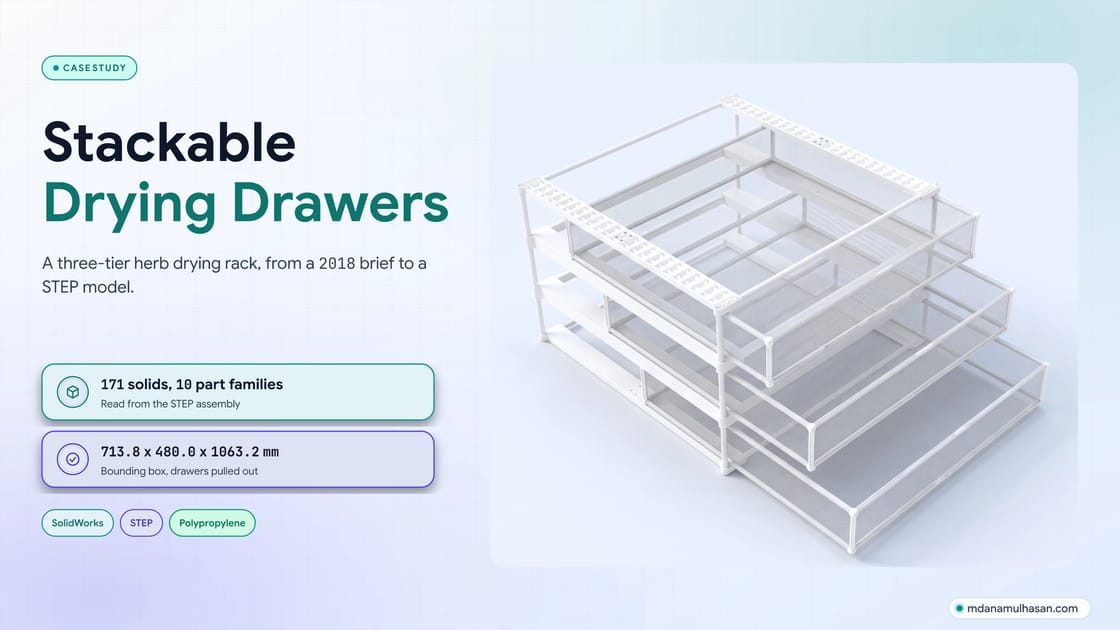
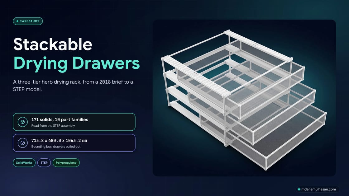
A three-tier herb drying rack: white frames with mesh drawers that slide out in steps, designed from a 2018 brief and modelled as a 171-solid STEP assembly in SolidWorks.
- Client
- Drying Drawer
- Role
- Designer
- Timeline
- Started Jan 2018
- Stack
- SolidWorks, STEP, Product design +3
Case study
Challenge & Solution
The brief
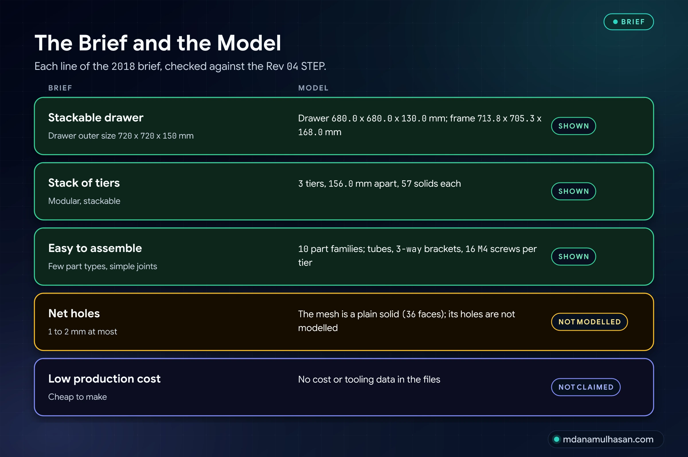
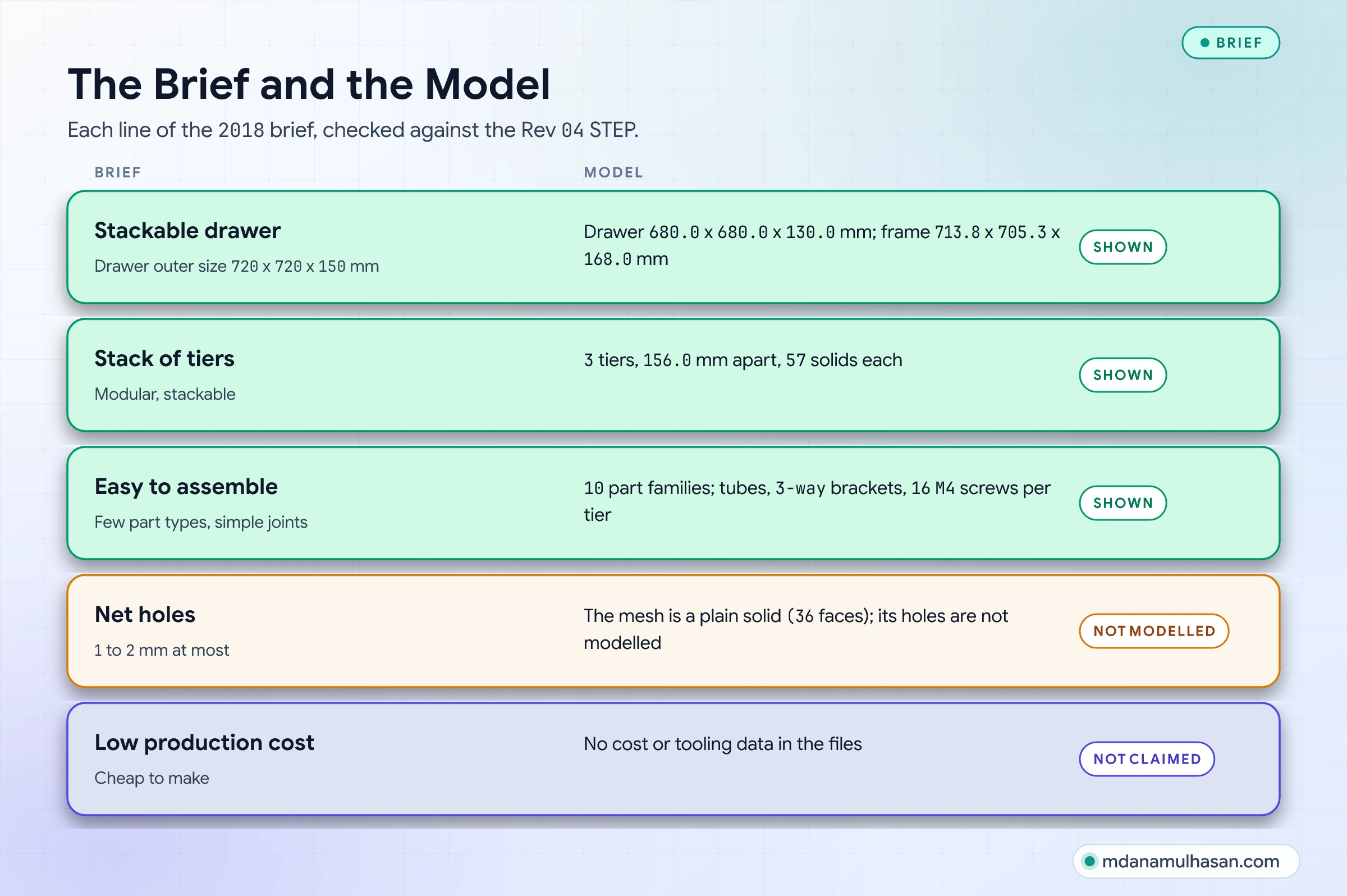
In January 2018 I got a brief for a stackable drying drawer for herbs: a net drawer that lets air reach the herbs from every side, stacks in tiers, is easy to assemble, and is cheap to make. It asked for manufacturing drawings, explanatory 3D views and input on how to make the parts. The outer size of a drawer was set at 72 x 72 x 15 cm, with net holes of 1 to 2 mm at most.
This case study follows the design from those sheets to the Rev 04 STEP model of a three-tier rack: three white frames, each with a mesh drawer that slides out on its side rails.
What the design shows
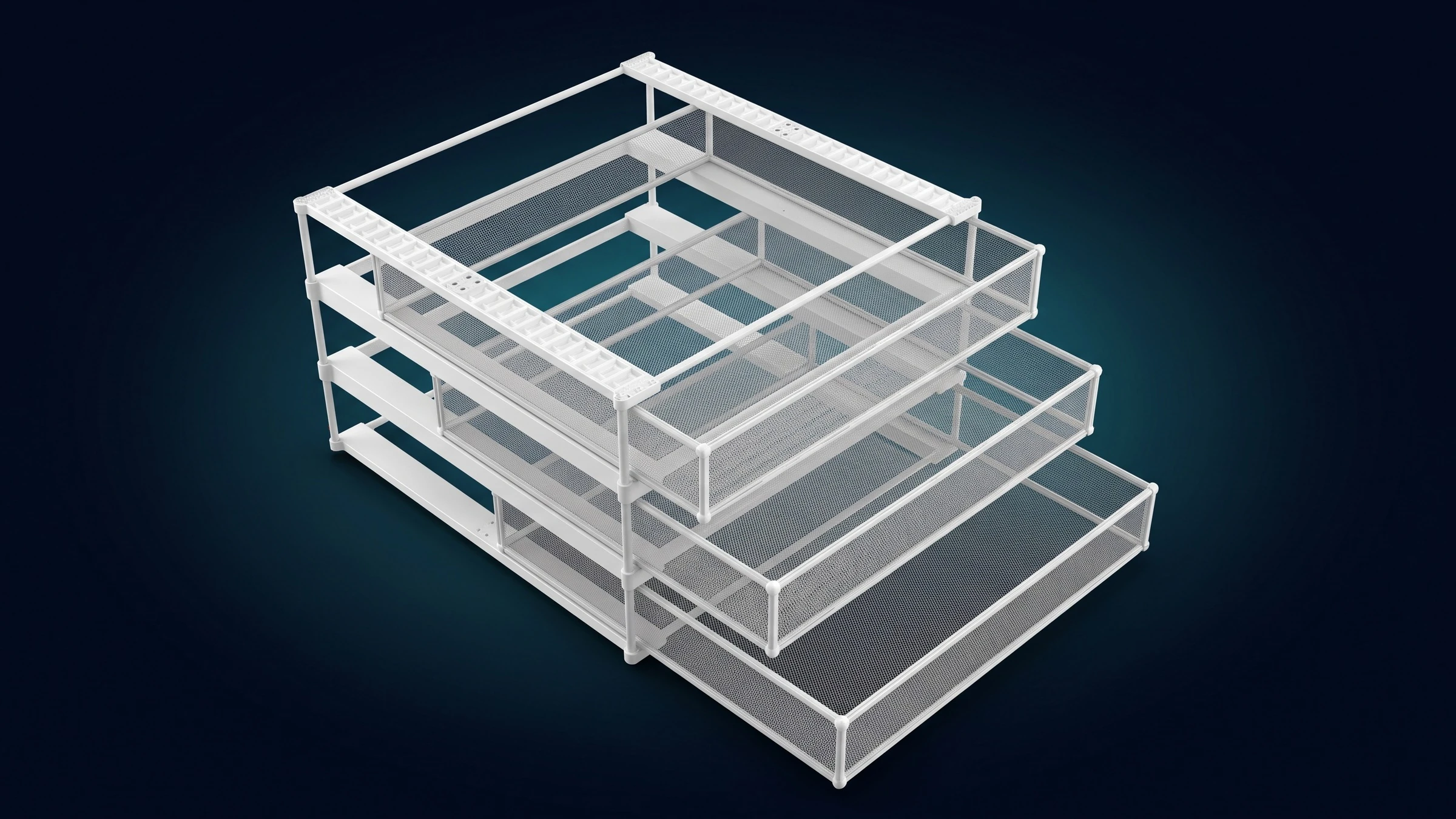
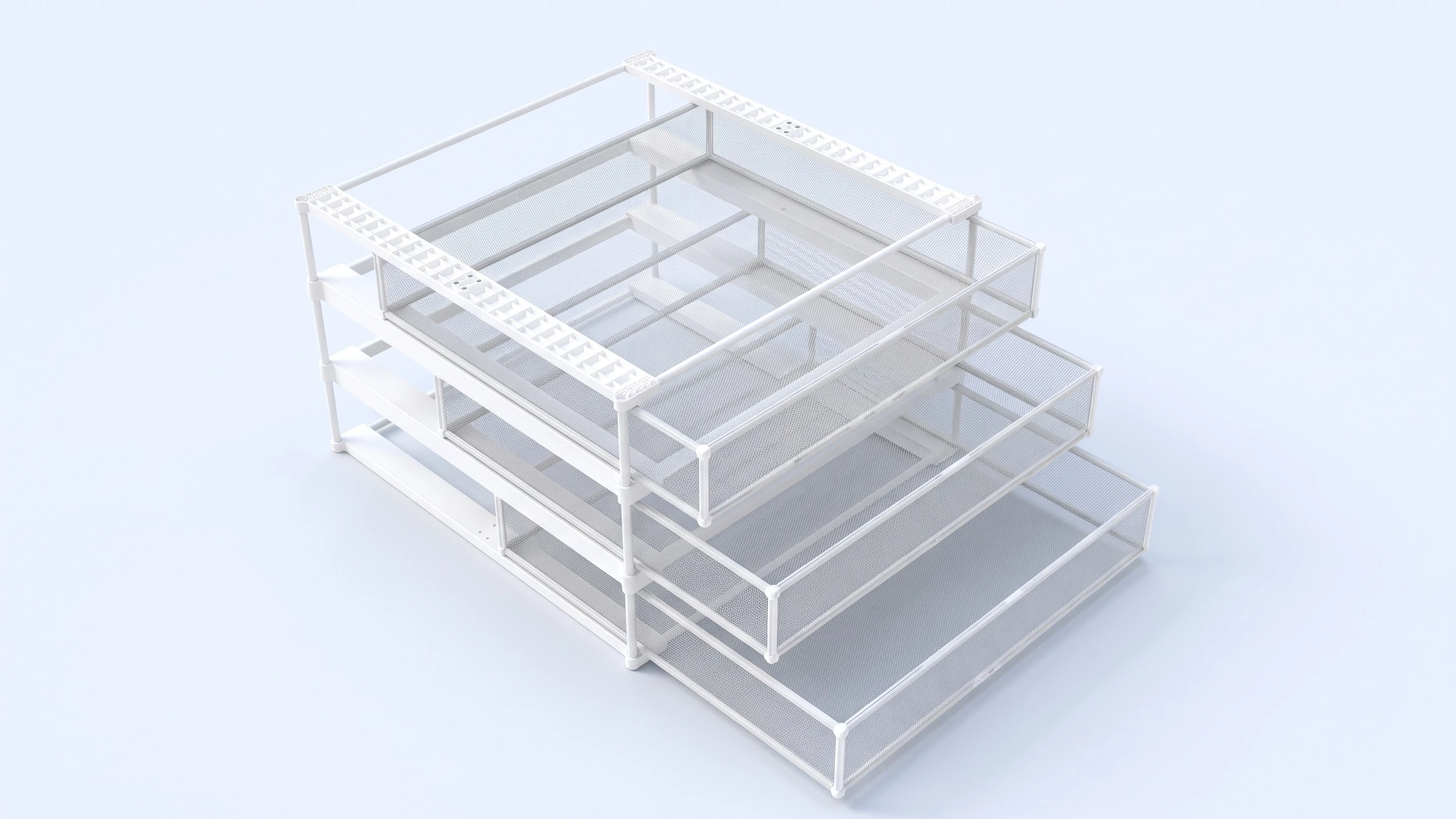
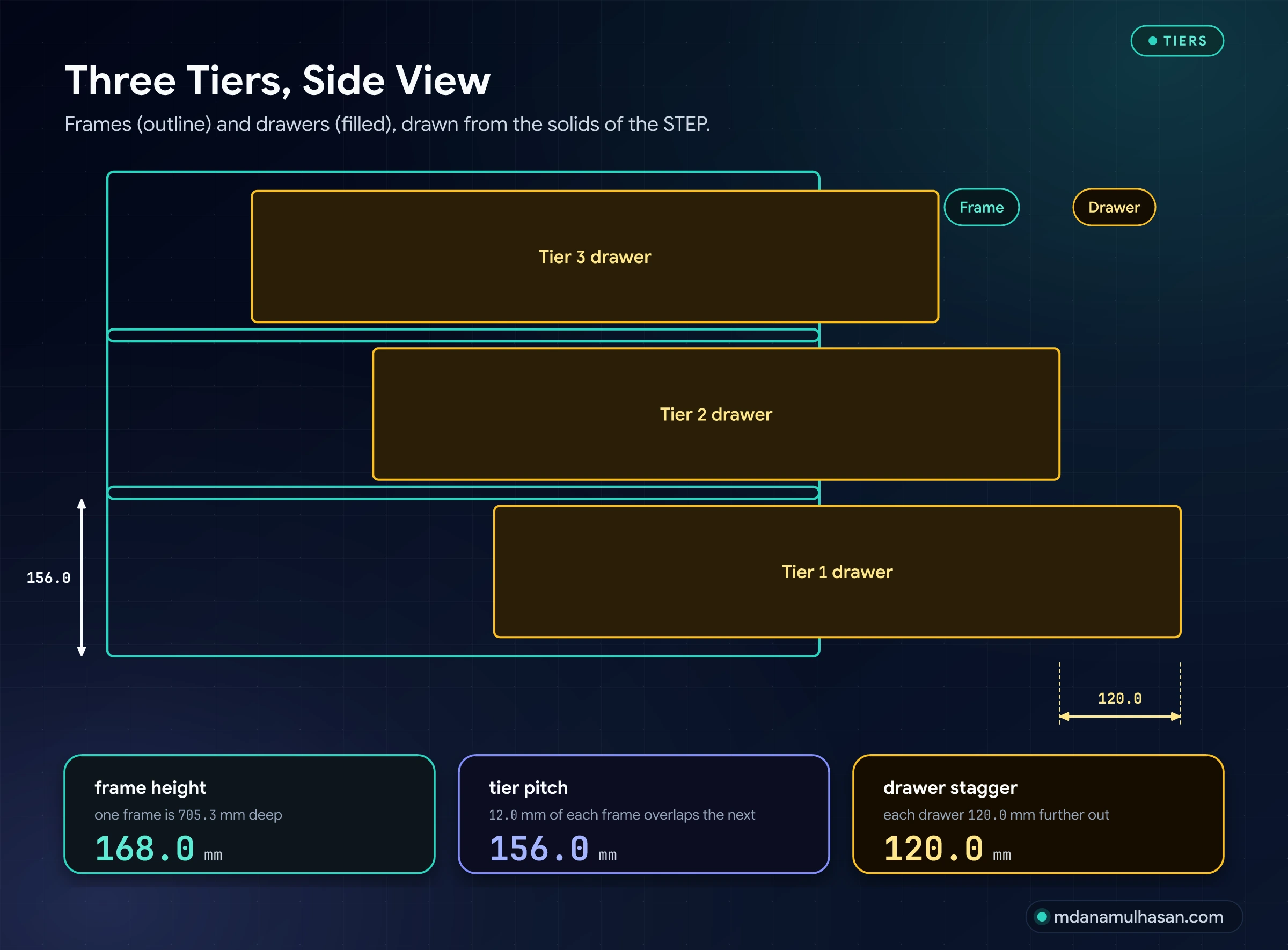
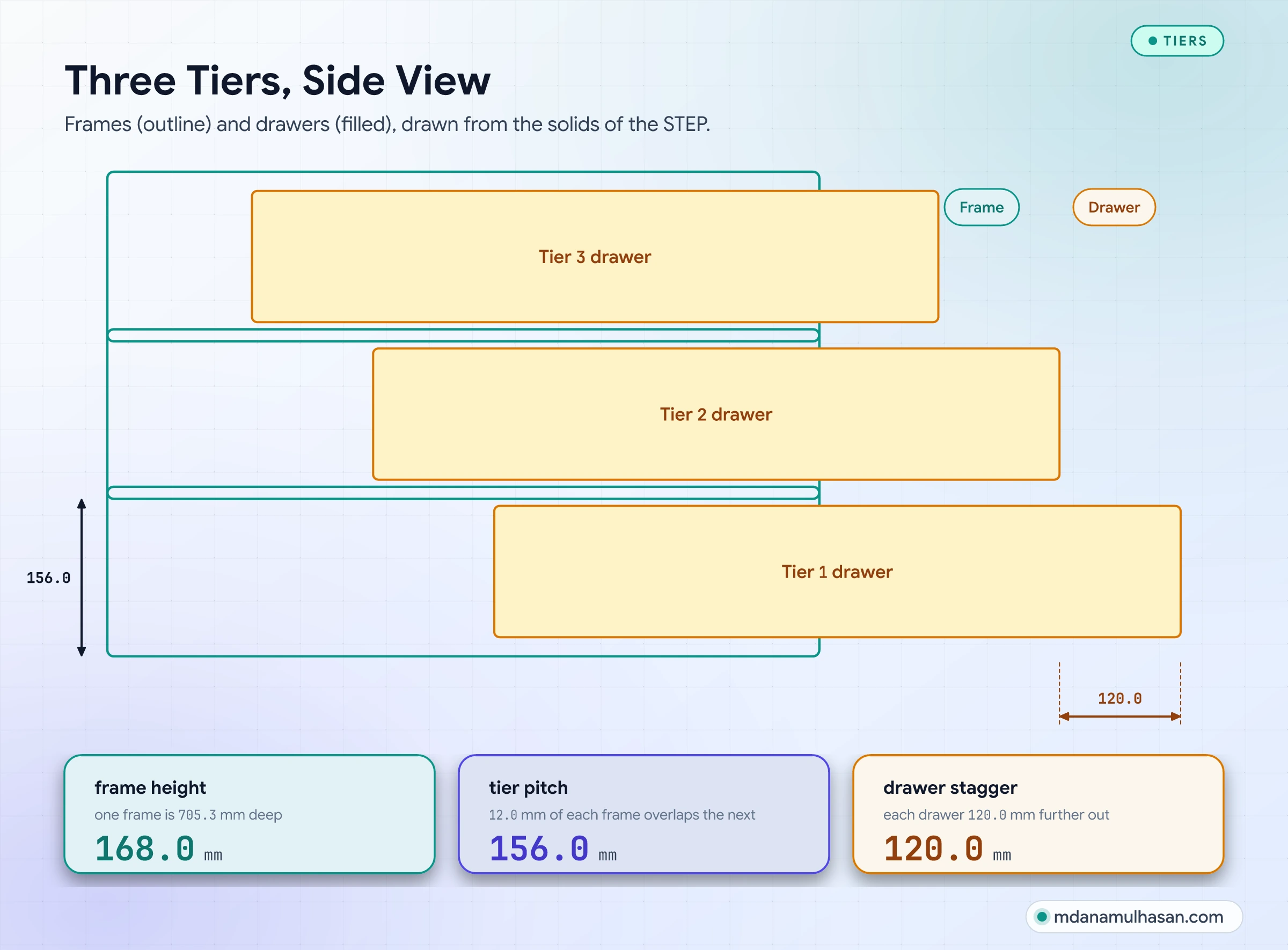
- Three tiers of one module. Each tier is a frame and a drawer. The frames sit 156.0 mm apart and each is 168.0 mm tall, so 12.0 mm of every frame overlaps the next.
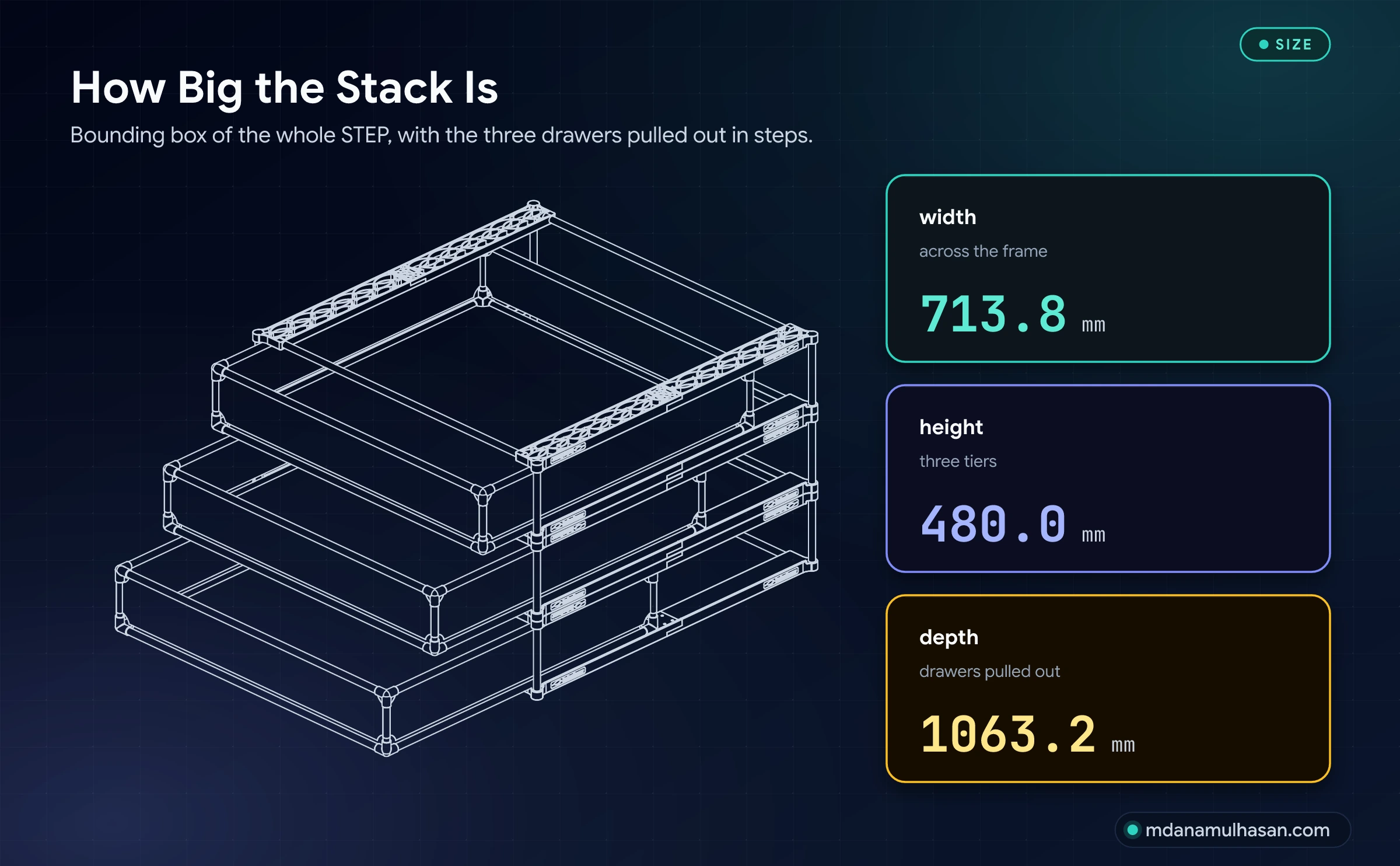
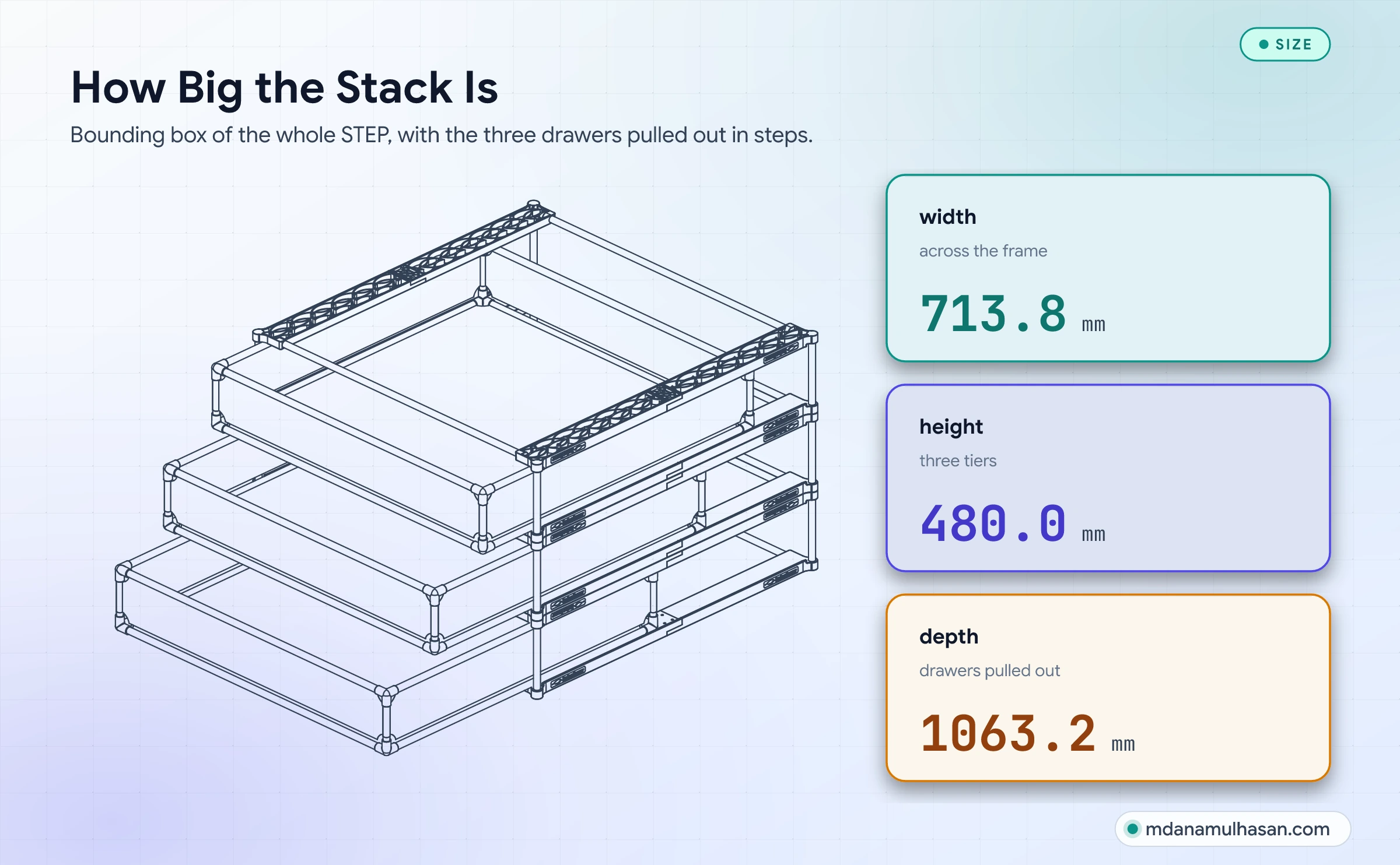
- Drawers that slide out in steps. In the model each drawer sits 120.0 mm further out than the one above it.
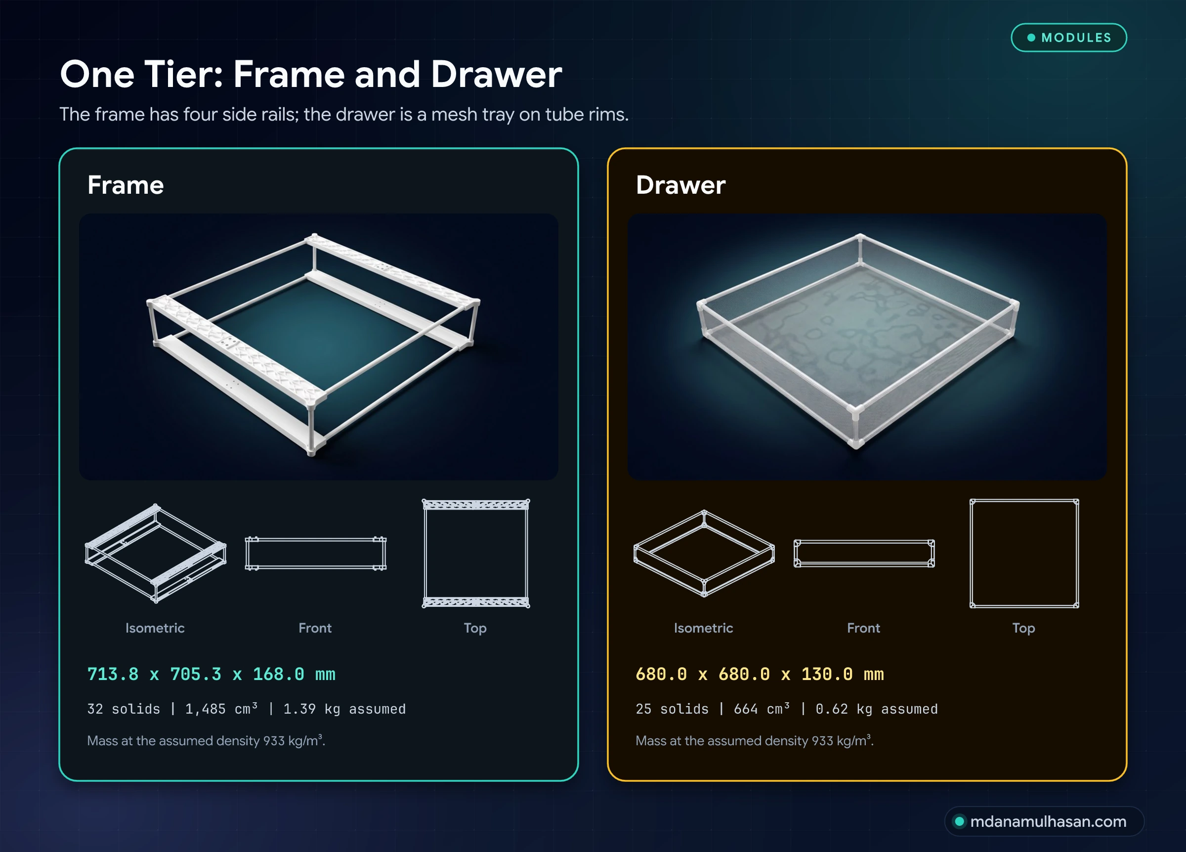
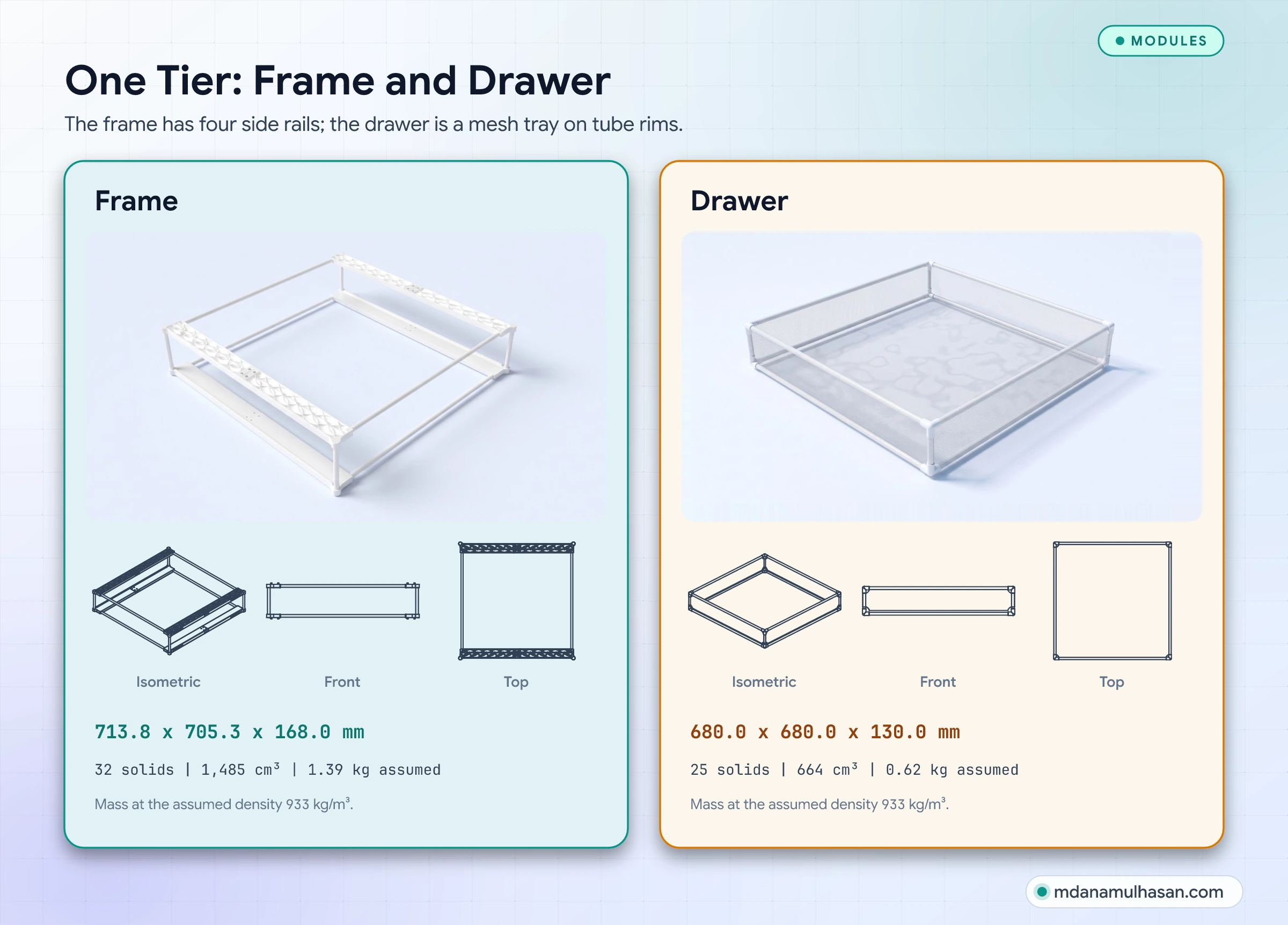
- Open mesh on every side. The drawer has a mesh floor and four mesh walls on a tube frame, so air can pass through the bottom and the sides.
- Tubes and joints instead of solid walls. The rims, posts and ties are round tubes, 12.5 mm across with a 3.0 mm wall, held at the corners by three-way brackets.
- Side rails with oval cut-outs. Each frame has four long side rails, an upper and a lower one on each side, and each rail is made of two halves joined with four M4 screws.
The whole assembly has 171 solids in 10 part families and measures 713.8 x 480.0 x 1063.2 mm with the drawers pulled out.
One tier: frame and drawer
The parts
Every size, count and volume comes from the STEP. Masses are computed at an assumed density of 933 kg/m³ (see “The material”).
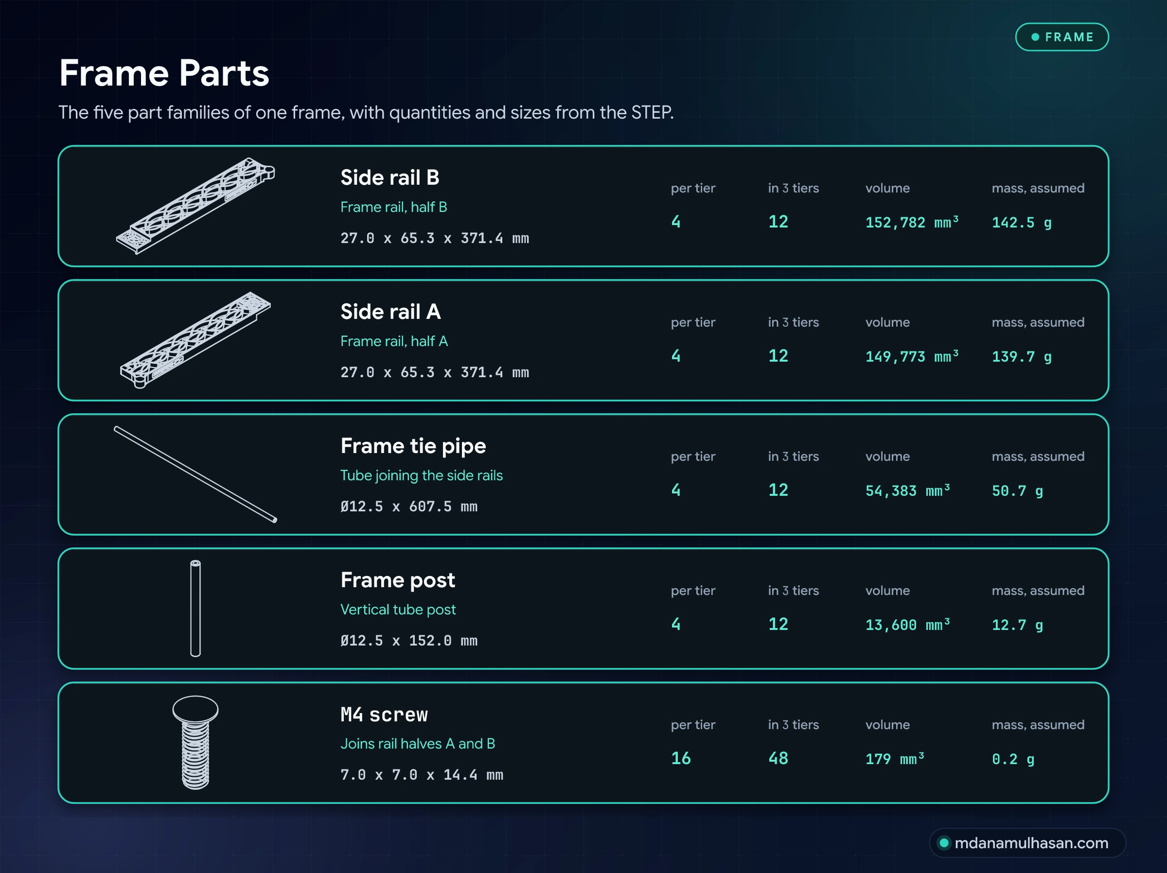
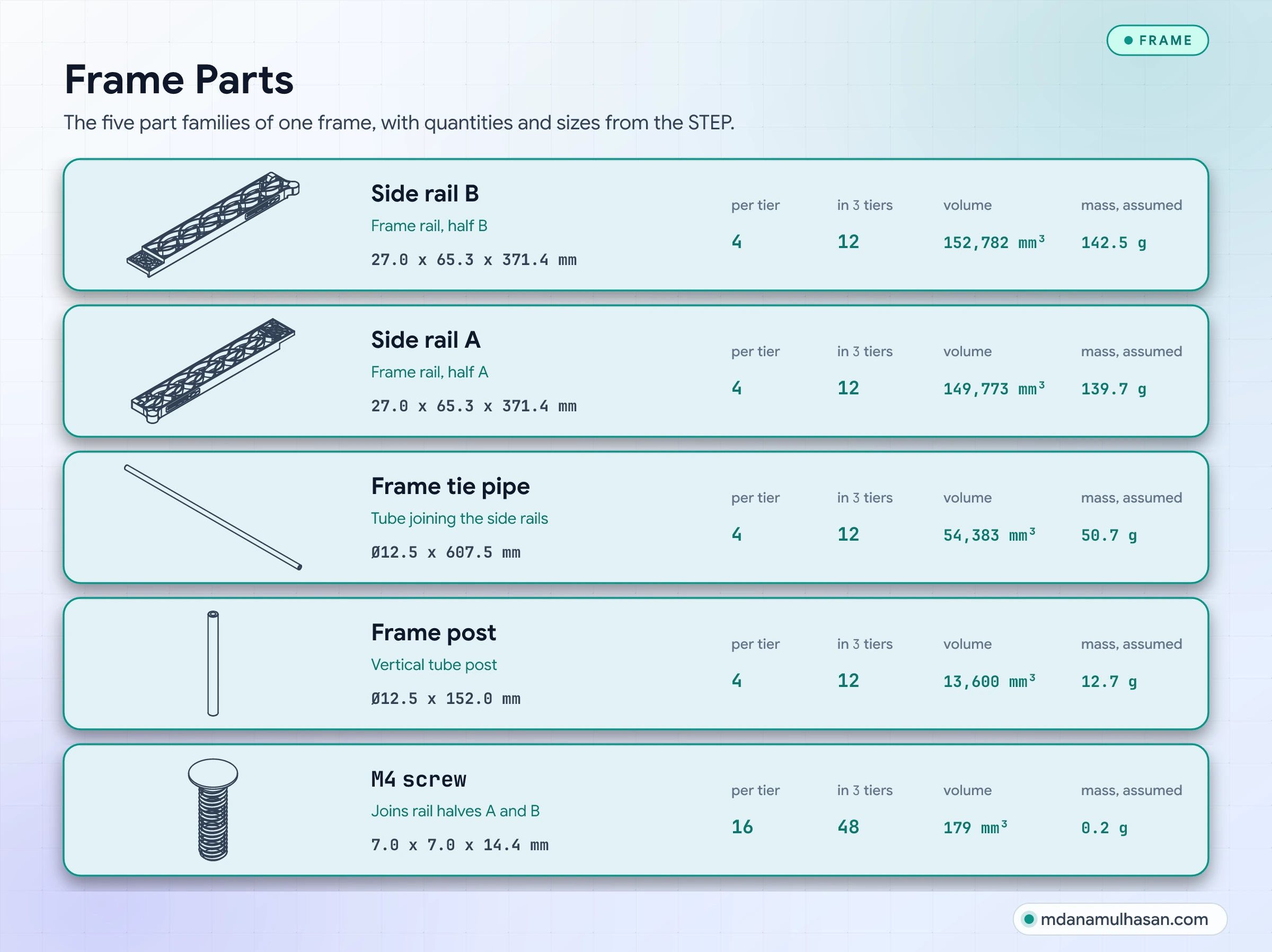
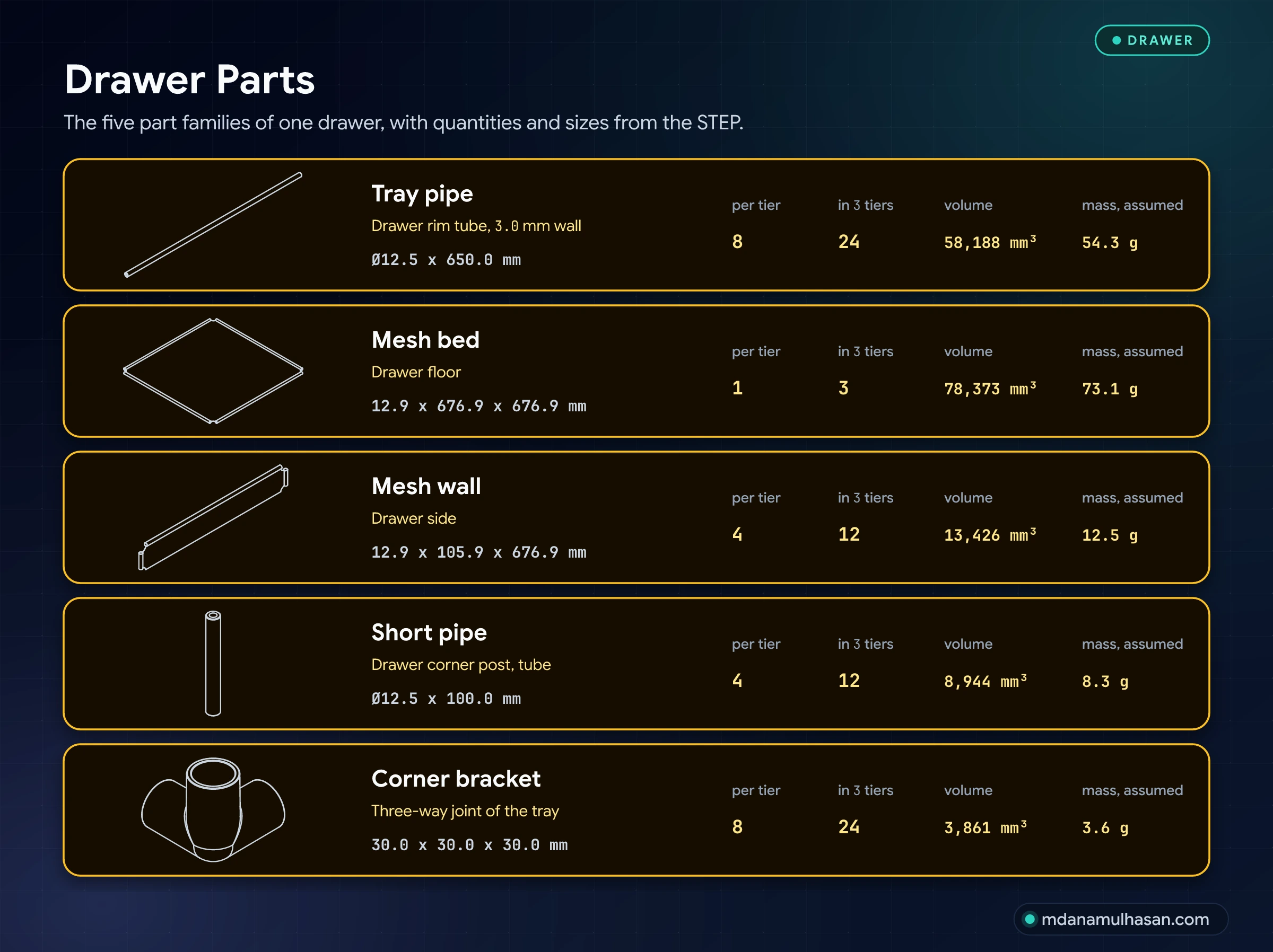
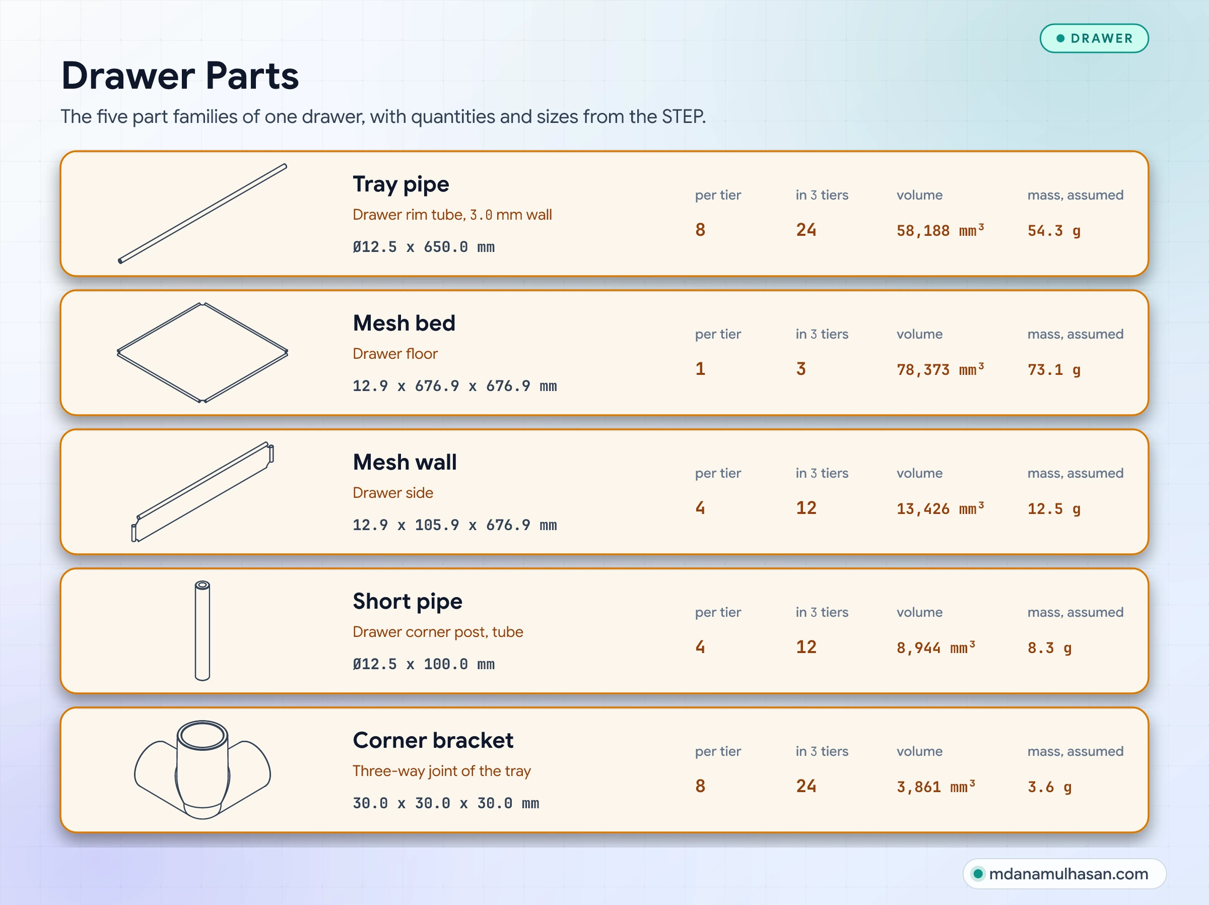
| Part | Size (mm) | Per tier | In 3 tiers |
|---|---|---|---|
| Side rail B | 27.0 x 65.3 x 371.4 | 4 | 12 |
| Side rail A | 27.0 x 65.3 x 371.4 | 4 | 12 |
| Frame tie pipe | Ø12.5 x 607.5 | 4 | 12 |
| Frame post | Ø12.5 x 152.0 | 4 | 12 |
| M4 screw | 7.0 x 7.0 x 14.4 | 16 | 48 |
| Tray pipe | Ø12.5 x 650.0 | 8 | 24 |
| Mesh bed | 12.9 x 676.9 x 676.9 | 1 | 3 |
| Mesh wall | 12.9 x 105.9 x 676.9 | 4 | 12 |
| Short pipe | Ø12.5 x 100.0 | 4 | 12 |
| Corner bracket | 30.0 x 30.0 x 30.0 | 8 | 24 |
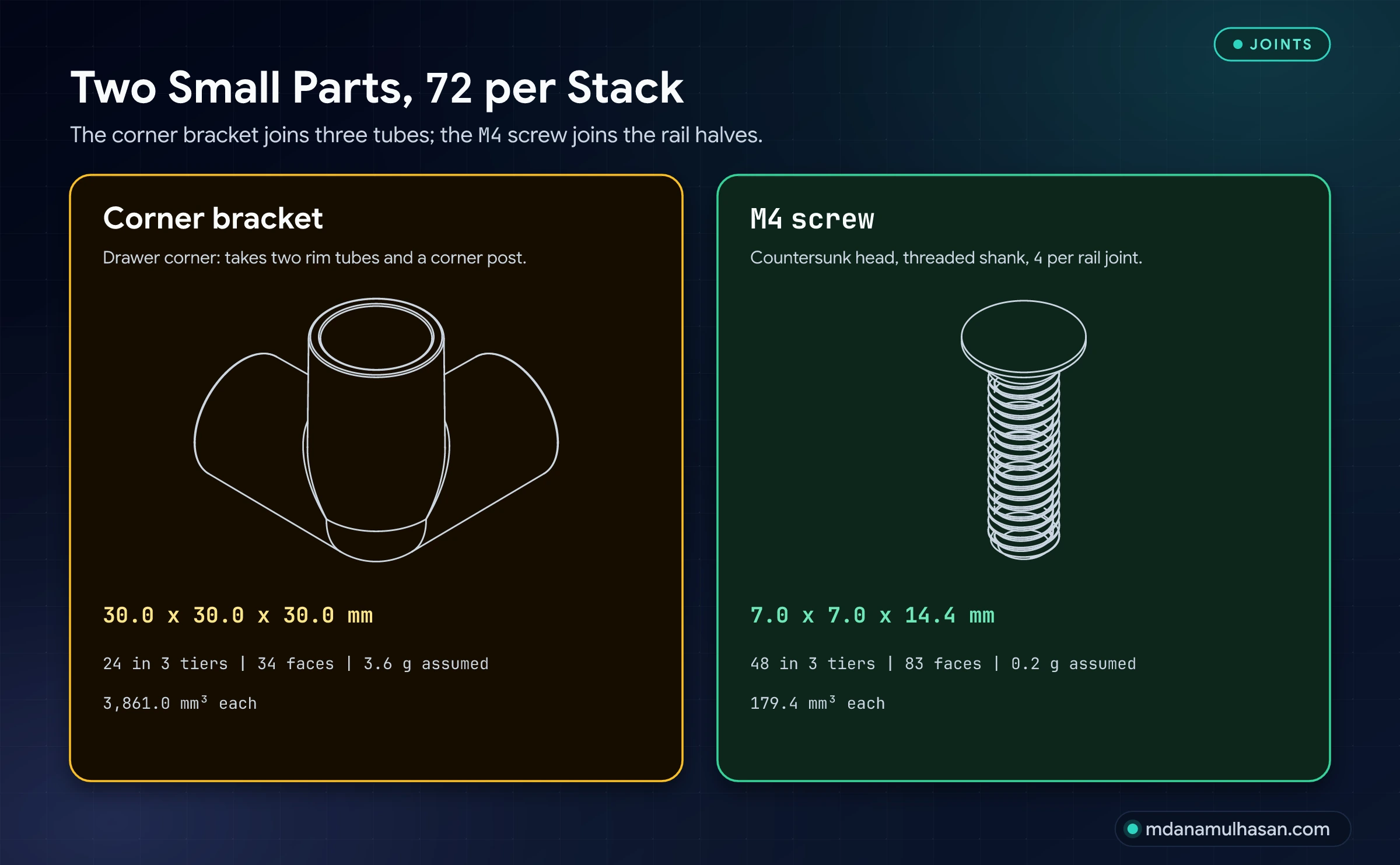
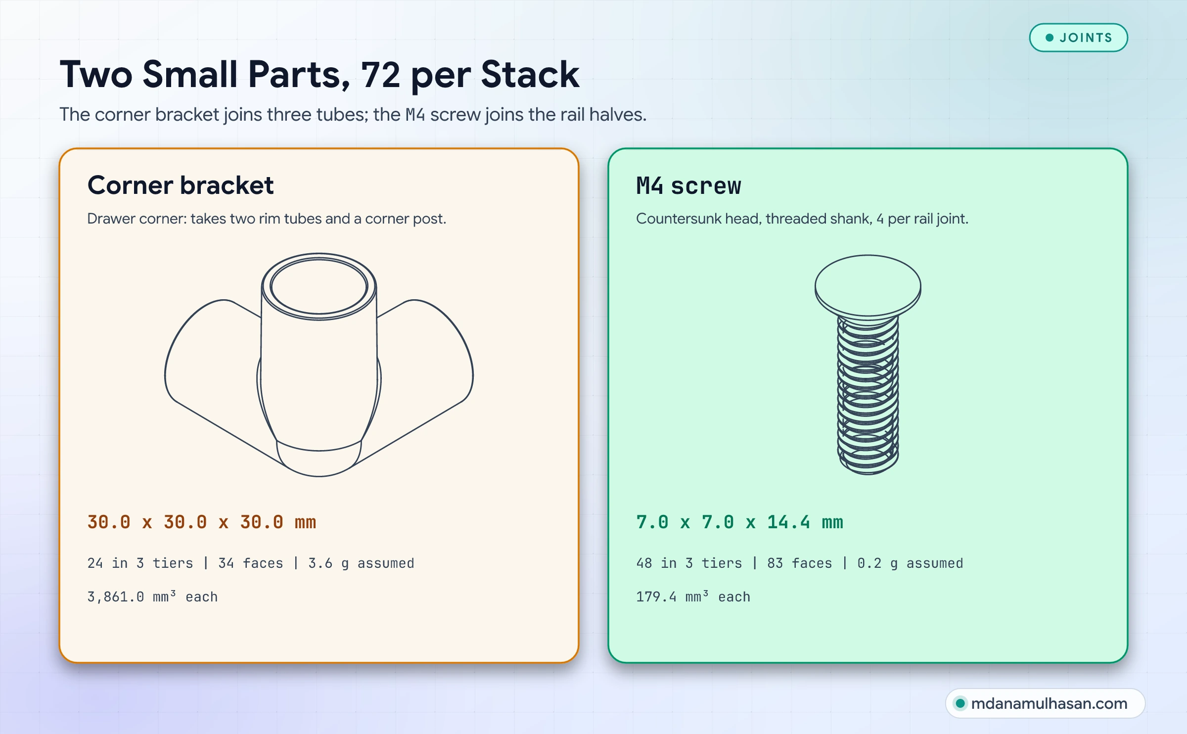
The corner bracket and the screw are 72 of the 171 solids. The mesh is modelled as plain solids with 36 faces, so the model does not show the weave or the 1 to 2 mm holes.
From one piece to two halves
My April 2018 drawing sheet shows the side panel as one piece, 720 mm long, 275.88 g, four per drawer. The June 2018 sheet splits it into two halves of 375.38 mm (130.11 g and 130.62 g). In the Rev 04 STEP the side rail is again two halves, A and B, each 371.4 mm long, overlapping by 37.6 mm and joined with four M4 screws.
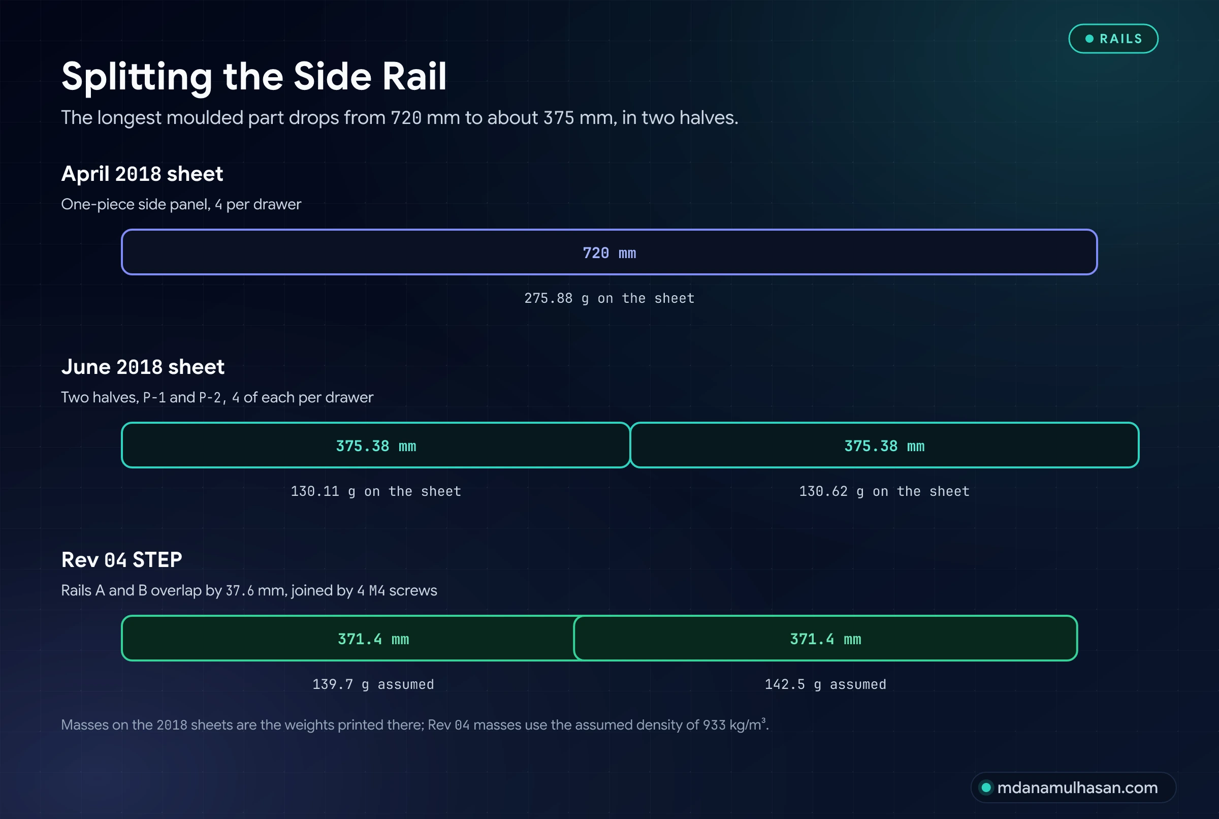
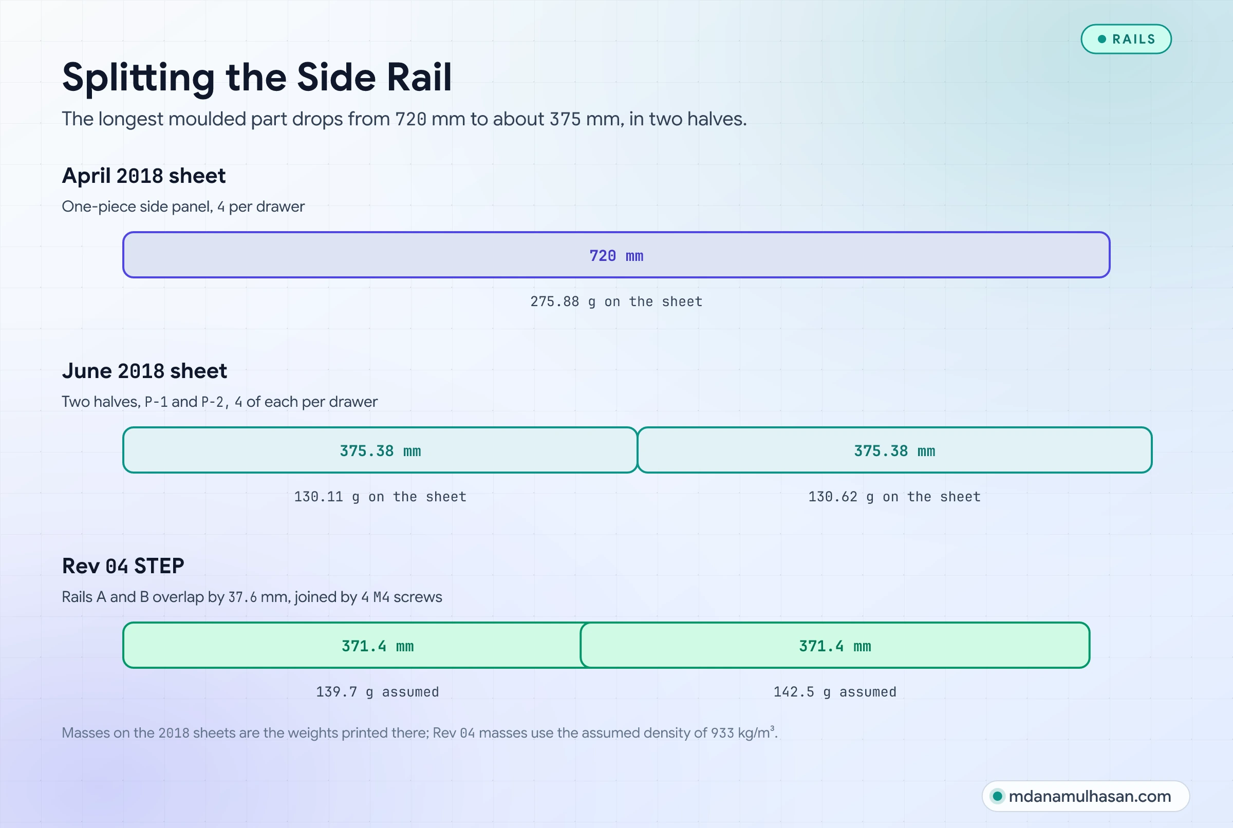
The longest moulded part falls from 720 mm to under 400 mm. A shorter part needs a smaller mould, which is the usual reason to split a long plastic part; the sheets do not record my reason, so I do not state one.
The material
My 2018 material sheet suggests polypropylene and lists its density (933 kg/m³), tensile strength (33 MPa) and compressive strength (39.3 MPa). It names no grade and no standard, so I treat the numbers as the sheet’s, not as checked values. Only the density is used here, and only to turn volumes into masses: the whole assembly is 6,447.8 cm³, which is 6.02 kg at 933 kg/m³.
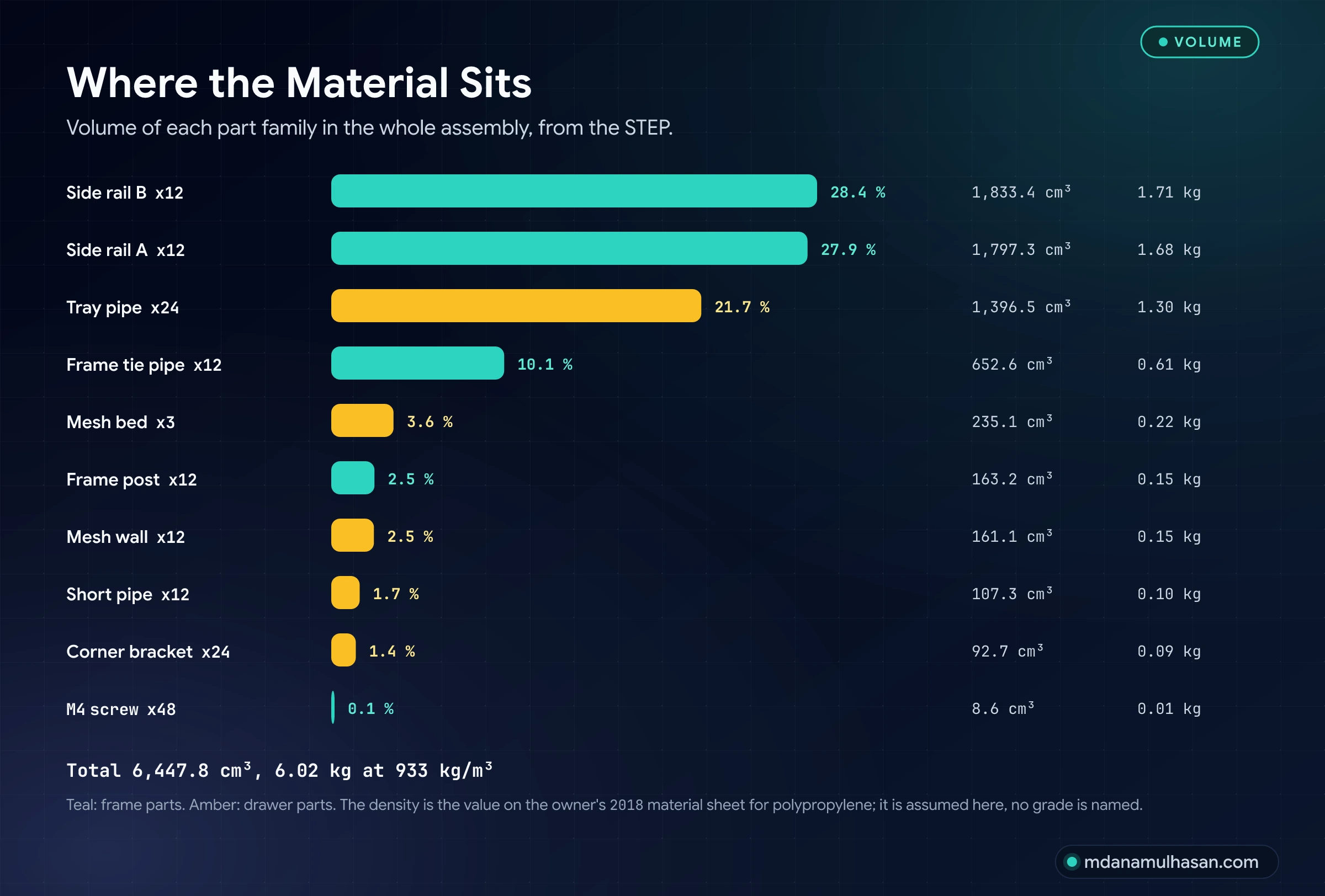
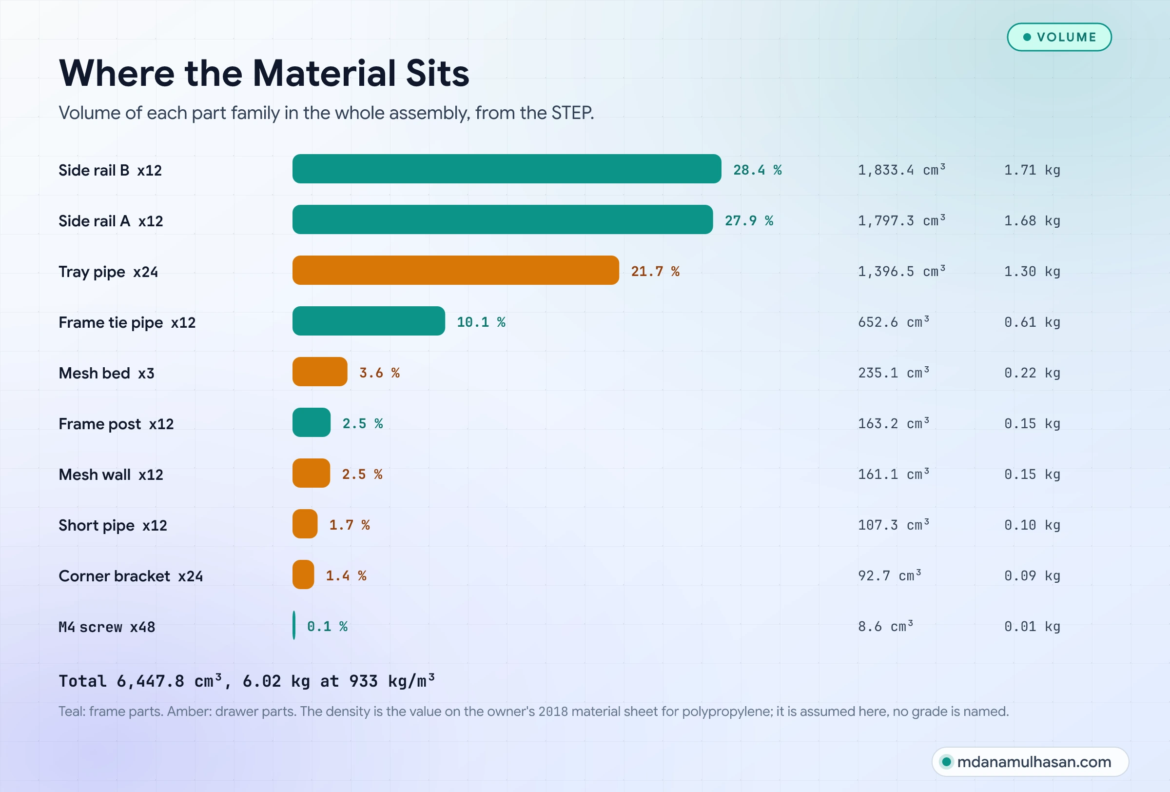
The side rails and the tray pipes hold about 78 percent of the volume.
The files behind it
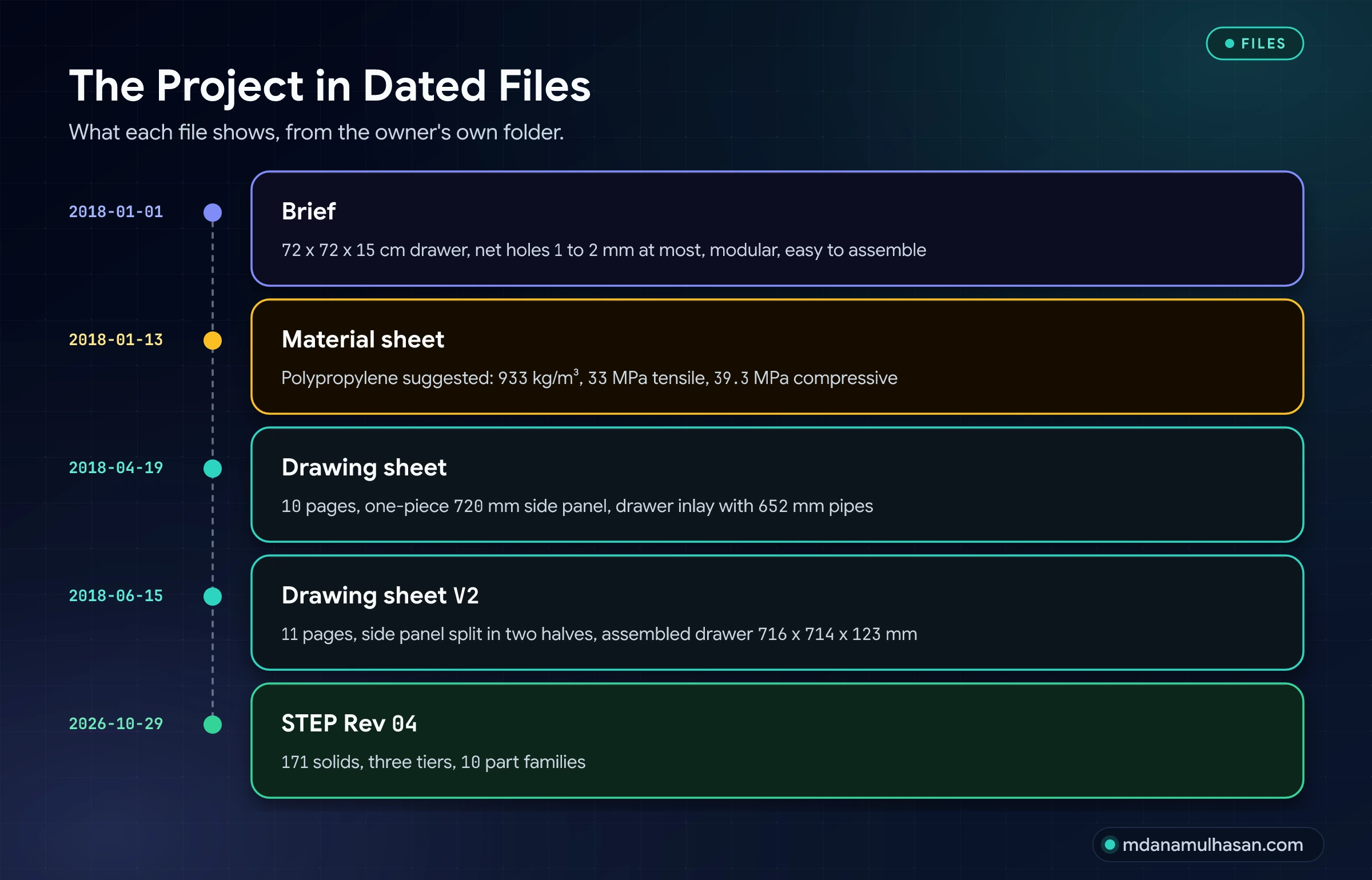
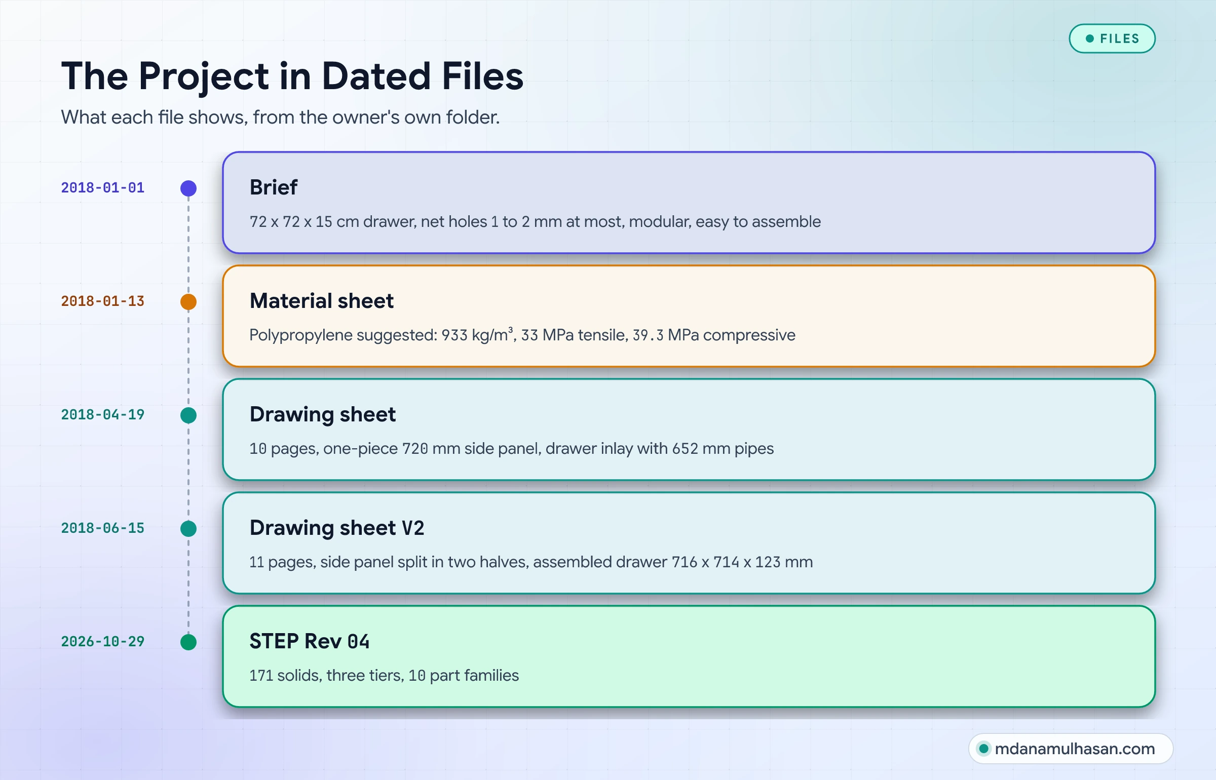
The dates are those stored in the files: the brief and the material sheet in January 2018, the drawing sheets in April and June 2018, and the STEP export of 29 October 2026.
In use
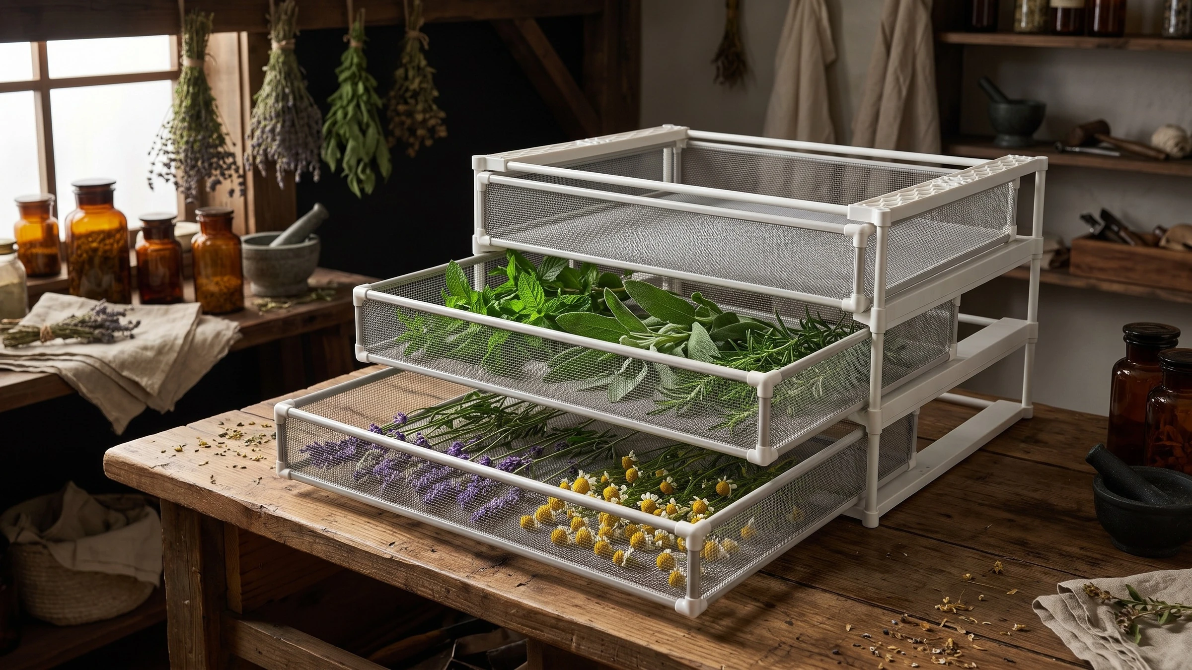
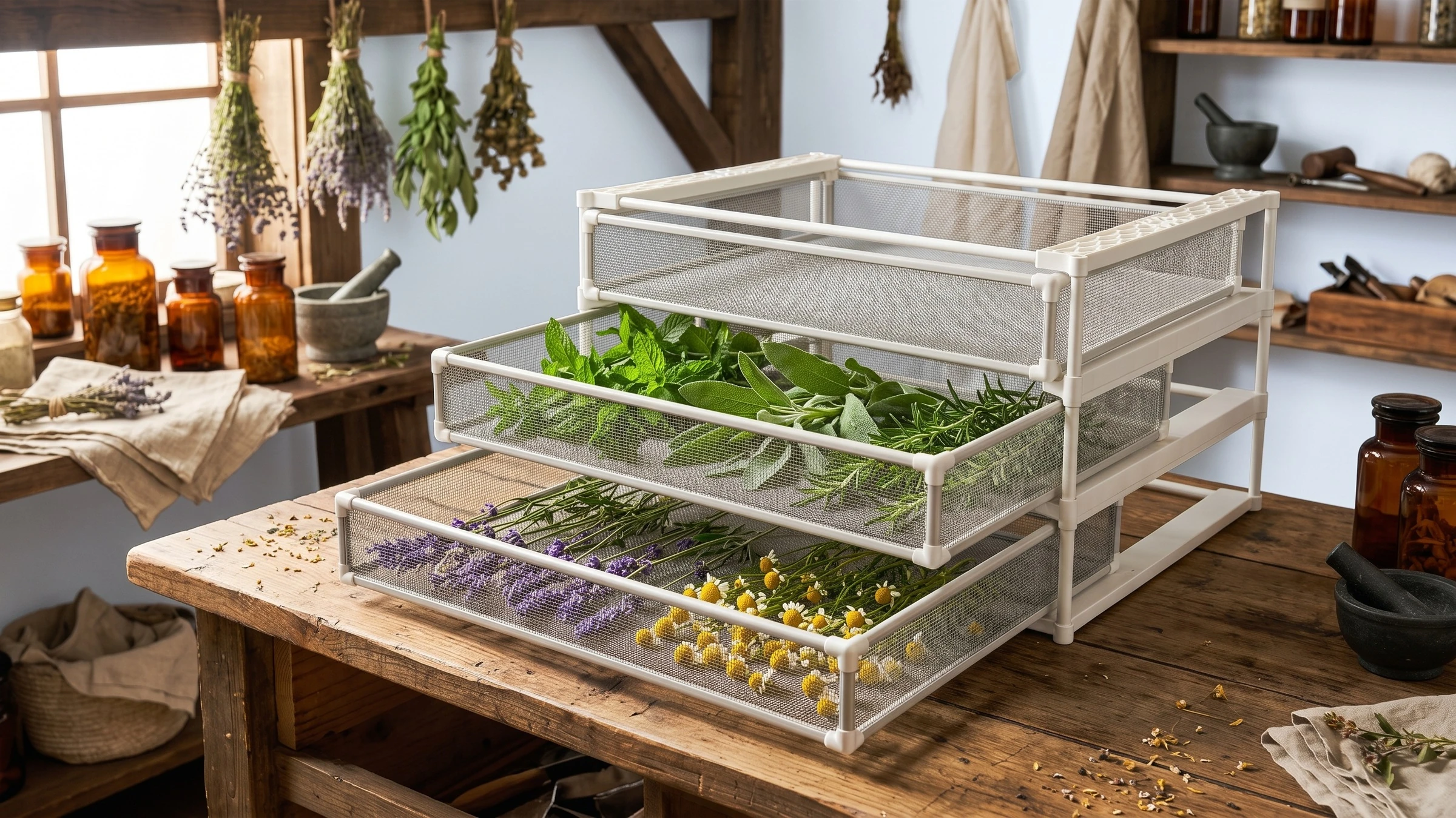
How the numbers were checked
The STEP was opened with a CAD kernel to read the bounding box, the solid and face counts and the volume of every solid. Tiers are found from the height of each solid (156.0 mm pitch), and every tier holds 57 solids: 32 in the frame and 25 in the drawer. The edge drawings and the side view are projected or drawn from those solids. The 2018 numbers (720 mm panel, 375.38 mm halves, weights, the brief) are read from my own sheets.
What this study does not claim
It gives no tooling layout, mould cost, draft angle, wall-thickness check of the rails, load test or airflow result: none of that is in the files. The brief’s 1 to 2 mm net holes are not modelled, so the model does not show that requirement. No prototype was built for this study. The studio images and the herb scene were generated from renders of the model with an image generator, so the weave of the mesh and the herbs are the generator’s, not CAD. The density is an assumption.
Links
Product design or a plastic part to split for moulding? Get in touch.
Another product housing, built as a prototype: Coffee Beater Enclosure. Designing parts to be made and assembled easily: the DFMA Design Handbook.
Measurable Impact
Key Outcomes & Performance
Quantified business outcomes and engineering improvements delivered.
Solids
In 10 part families: three tiers of 57 solids, 32 in the frame and 25 in the drawer
Assembled size
Depth of the STEP with the drawers pulled out; 713.8 mm wide and 480.0 mm high
Mass
Whole assembly at an assumed 933 kg/m³ for polypropylene
Visual Documentation
Project Gallery & Technical Visuals
High-precision 3D CAD renders, exploded assemblies, and fabrication documentation.
Process & Milestones
Engineering & Development Journey
From initial requirements gathering to precision modeling and manufacturing validation.
Read the brief
Jan 2018A net drawer for herbs: 72 x 72 x 15 cm, net holes of 1 to 2 mm, modular and easy to assemble.
Draw and split the parts
Apr-Jun 2018Polypropylene suggested; a one-piece 720 mm side panel in April, split into two halves in June.
Model three tiers
STEPThree frames and three drawers as one STEP assembly: 171 solids in 10 part families.
Visualise the rack
RenderStudio visualisations of the rack and of herbs drying in the pulled-out drawers.
Technical Stack
Technologies, Tools & Frameworks
Explore Further
More Engineering Case Studies


Coffee Beater Enclosure: Designing a Hand-Held Beater from CAD to Prototype
The housing of a hand-held coffee beater: a two-section faceted enclosure, a nose-cone coupler and an internal spacer, modelled in SolidWorks, rendered, and built as a prototype.


Engine Oil Bottle Family: Designing 1, 2, 4 and 5 Litre Blow-Molded Bottles
A family of four engine oil bottles, 1, 2, 4 and 5 litres, designed in 2017 as one scaled blow-molded shape with a separate cap, modelled in SolidWorks and rendered in KeyShot.