
Metric and unified inch threads on three A4 pages
A free three-page A4 size chart for bolt and screw threads: the metric threads M1 to M64 of ISO 261 with pitch and minor diameters, stress area and tap drill, and the unified UNC and UNF threads of ASME B1.1 from #0 to 4 in.
bolt-screw-size-chart.pdf
- Type
- Chart
- Format
- Download size
- 61 KB PDF
- Price
- Free
- License
- Free to use
What the chart covers
Metric threads
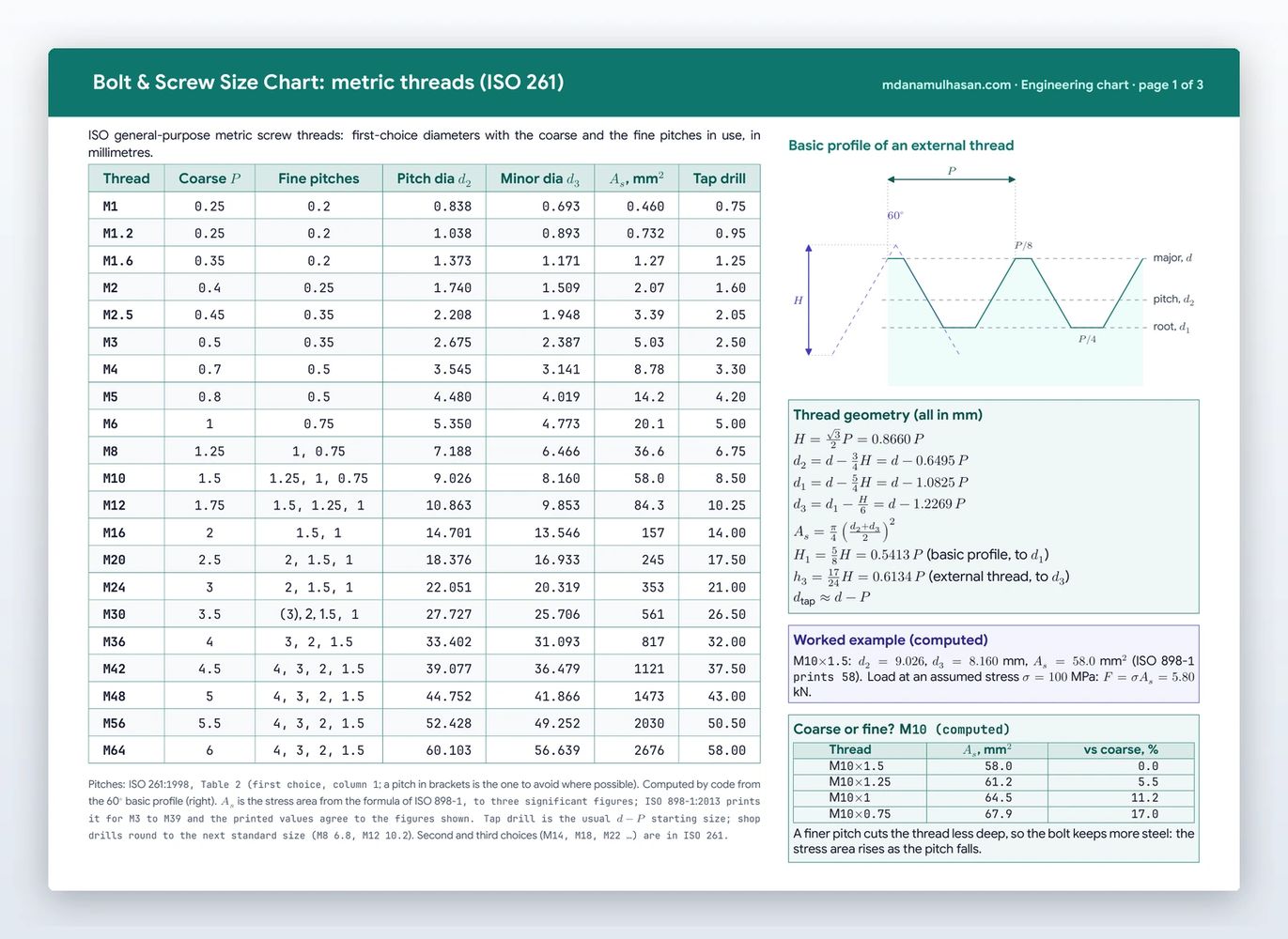
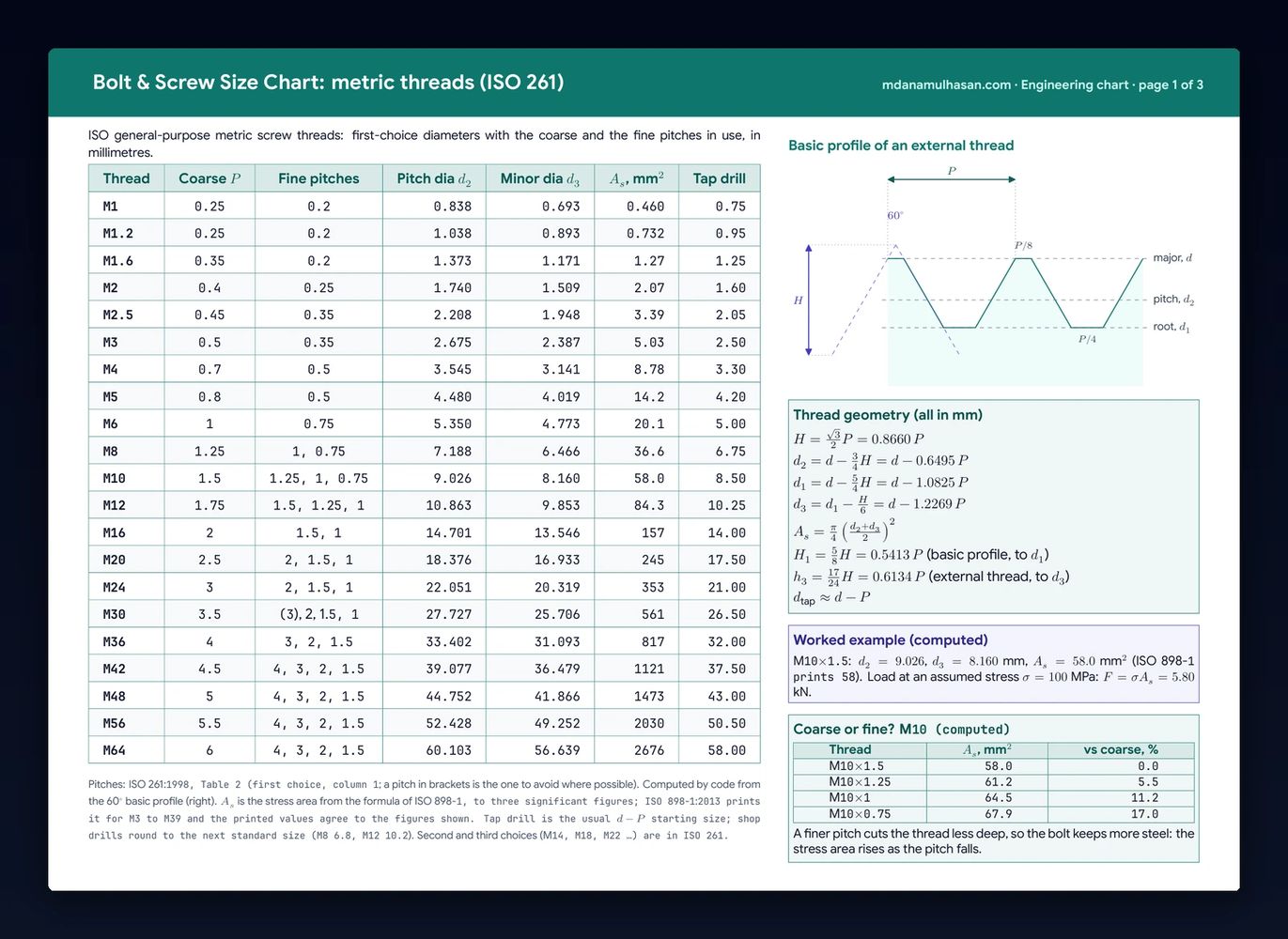
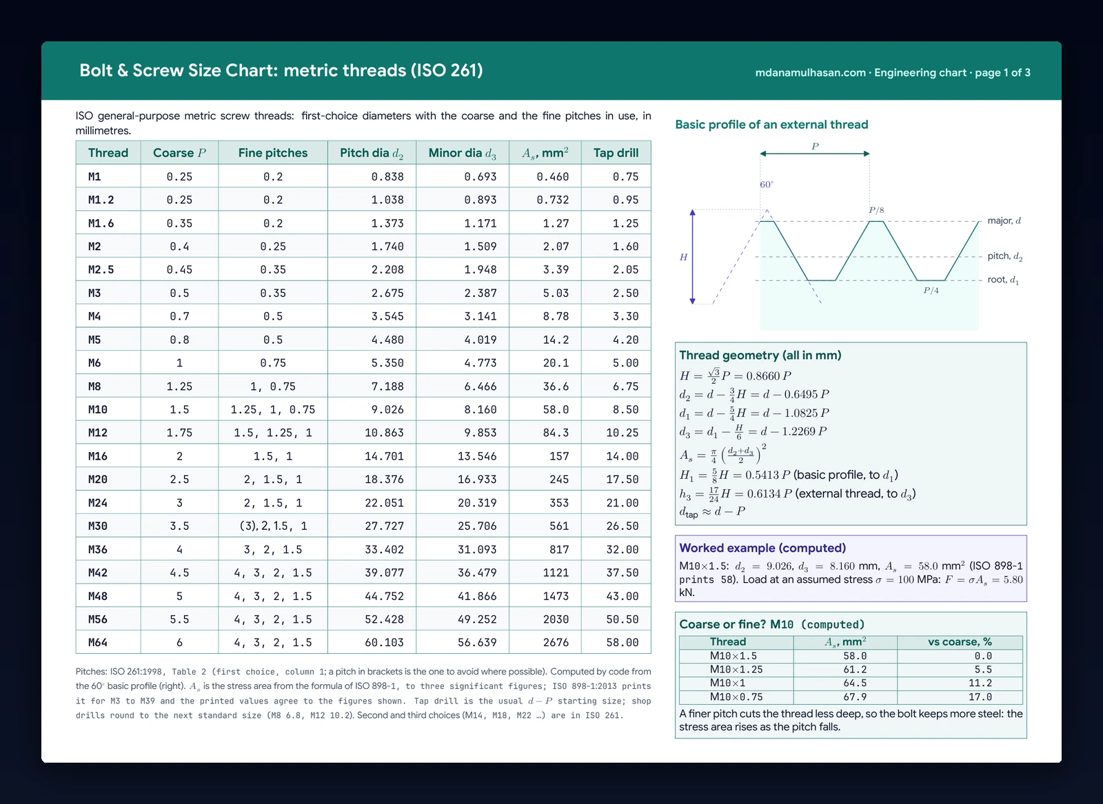
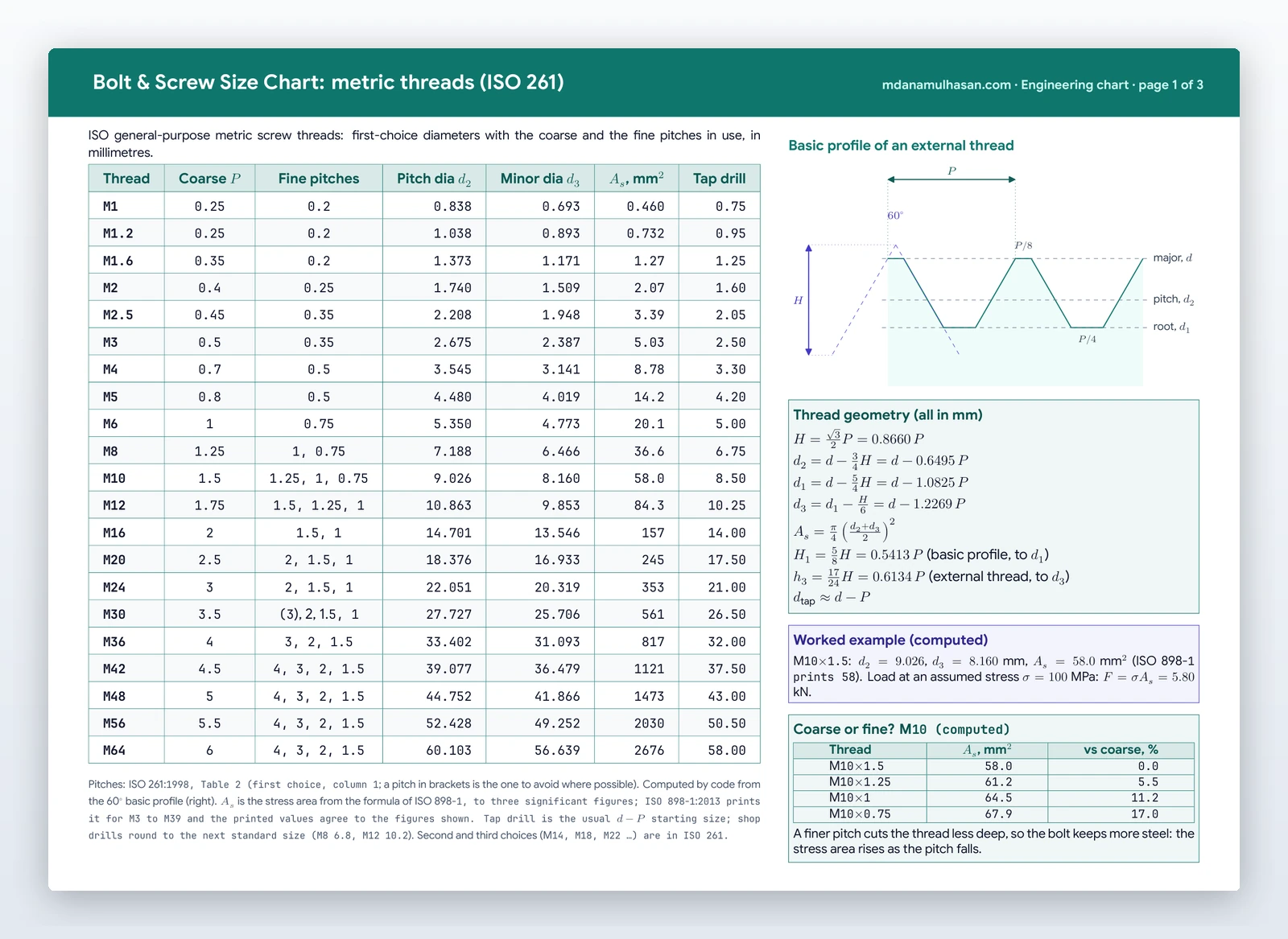
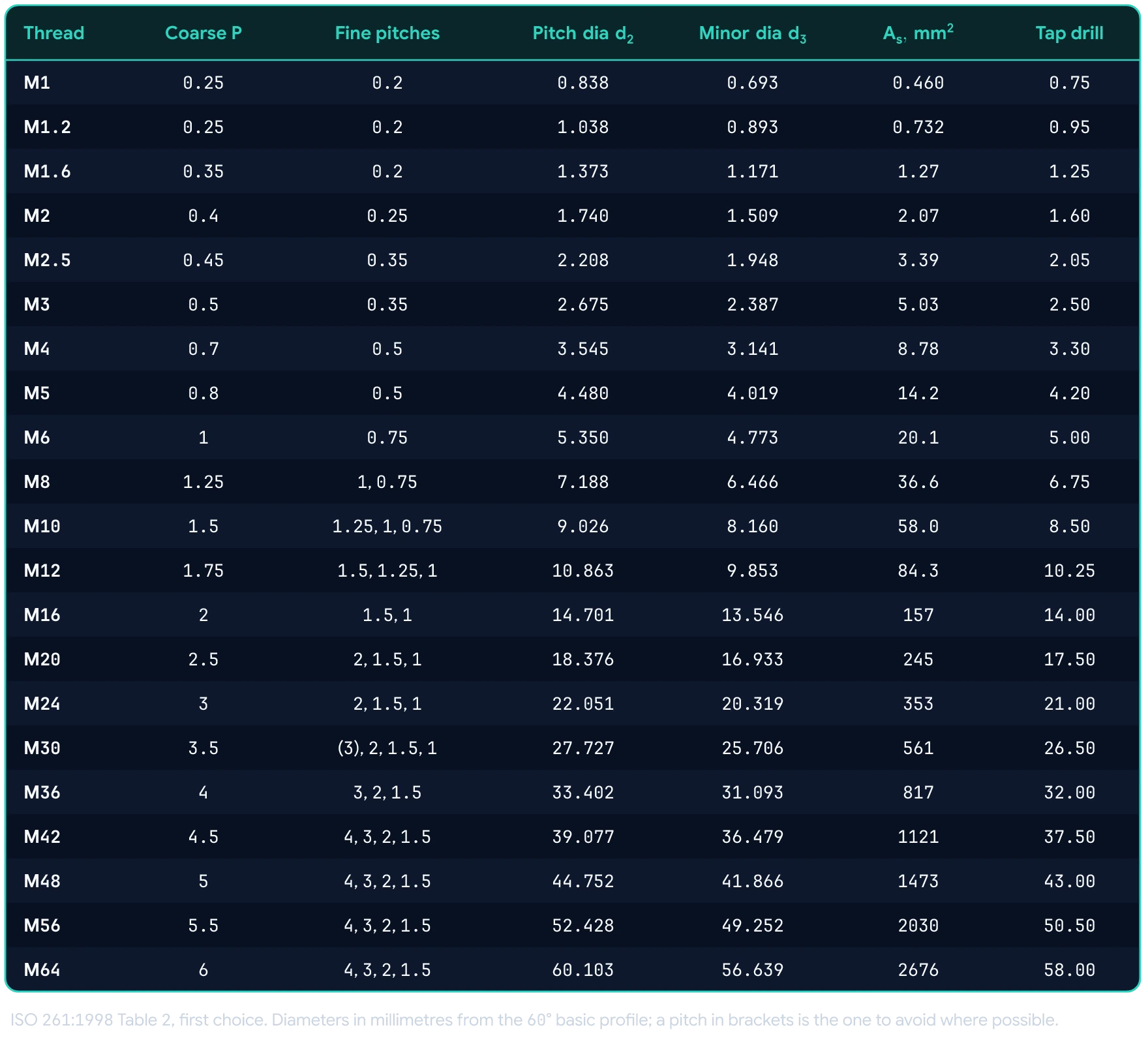
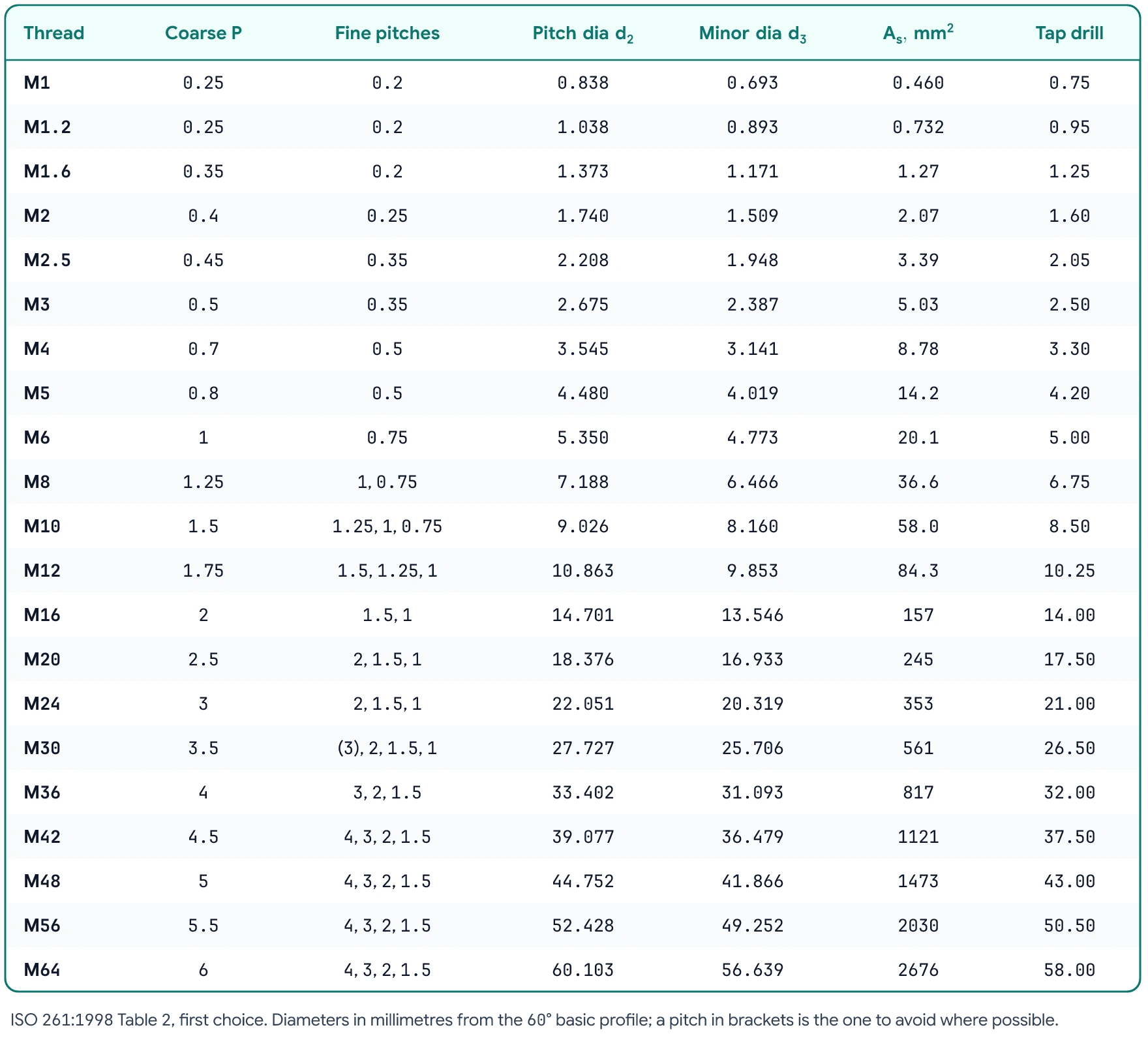
21 first-choice sizes with coarse and fine pitches, pitch and minor diameters and stress area, from ISO 261.
Unified threads
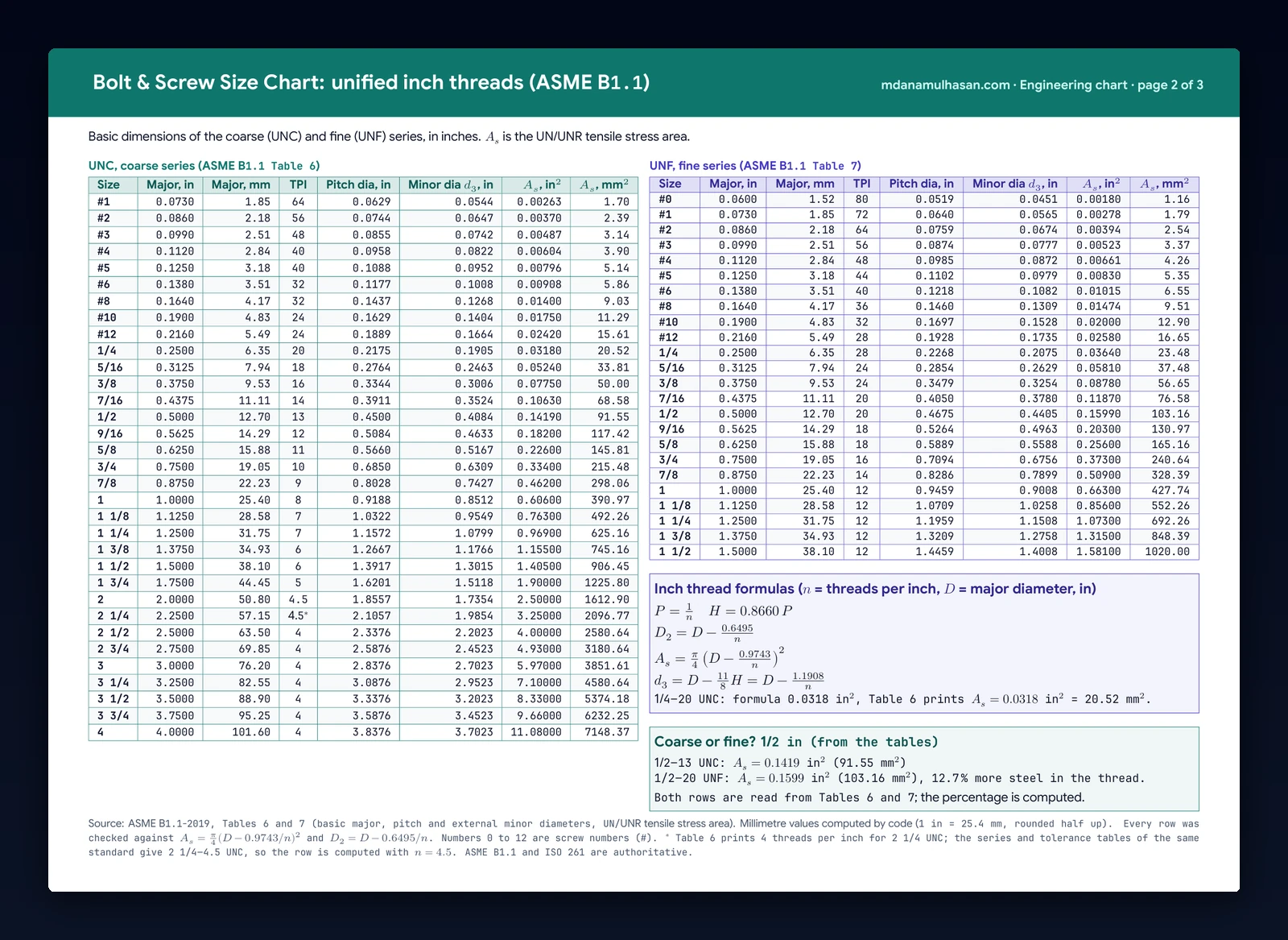
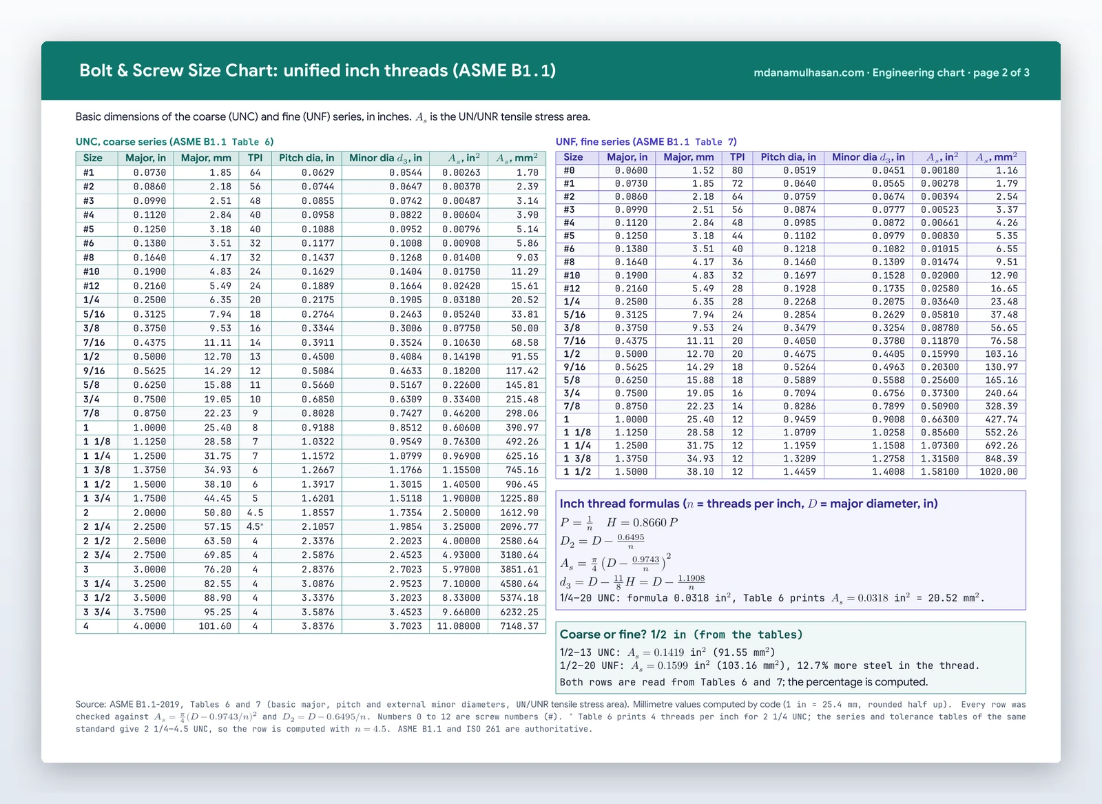
UNC #1 to 4 in and UNF #0 to 1 1/2 in with pitch and minor diameter and tensile stress area, from ASME B1.1.
Thread profile
The 60 degree basic profile with the formulas for every diameter.
Stress area
In square millimetres for every size, with the load a thread carries.
Inch against metric
Seven inch sizes against the nearest metric thread.
Read from the standards
Pitches and inch dimensions are read from ISO 261 and ASME B1.1; computed values are labelled.
Using the chart
- 01
Download the PDF
Enter your name and email and the link arrives at once.
- 02
Find the size
Look up the metric or the inch thread on page 1 or 2.
- 03
Check the load
Take the stress area and the bolt class and read the load on page 3.
A free three-page A4 size chart for bolt and screw threads: the 21 first-choice ISO metric threads M1 to M64 with coarse and fine pitches, pitch and minor diameters, stress area and tap drill, and the unified inch threads UNC and UNF from #0 to 4 in with pitch and minor diameters and tensile stress area. The pitches and the inch dimensions are read from ISO 261:1998 and ASME B1.1-2019; the metric diameters and stress areas are computed from the 60° basic profile with the formulas printed on the chart, so the numbers on the wall and on the screen cannot disagree.
What is on the chart
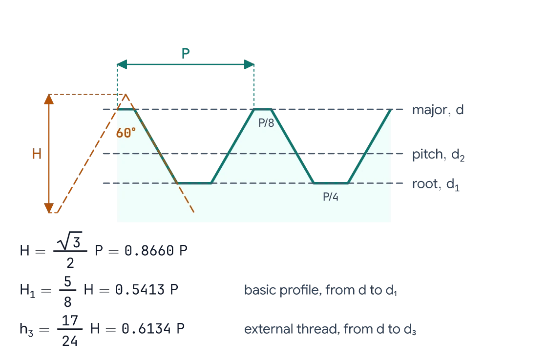
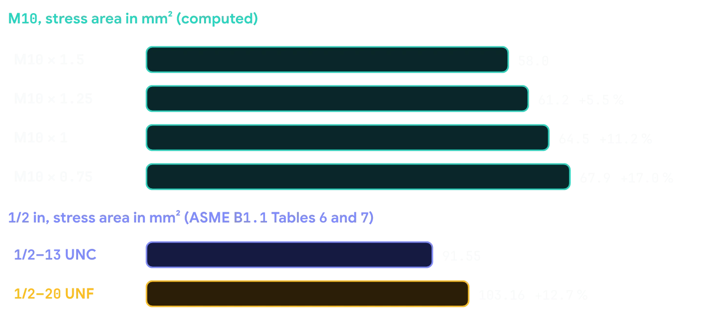
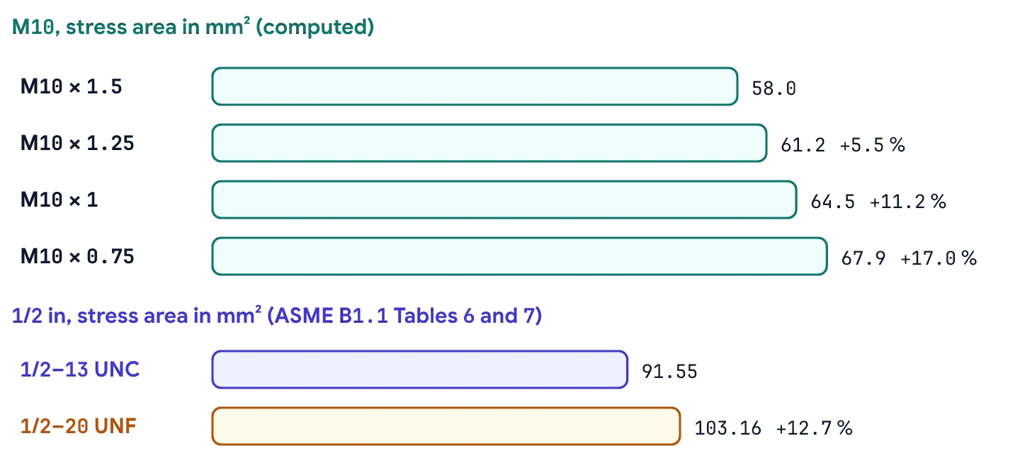
- Page 1. The 21 first-choice metric threads M1 to M64 with coarse pitch, fine pitches, pitch diameter, minor diameter, stress area and tap drill, the 60° basic profile, the geometry formulas, an M10×1.5 load example and the stress area of M10 with four pitches.
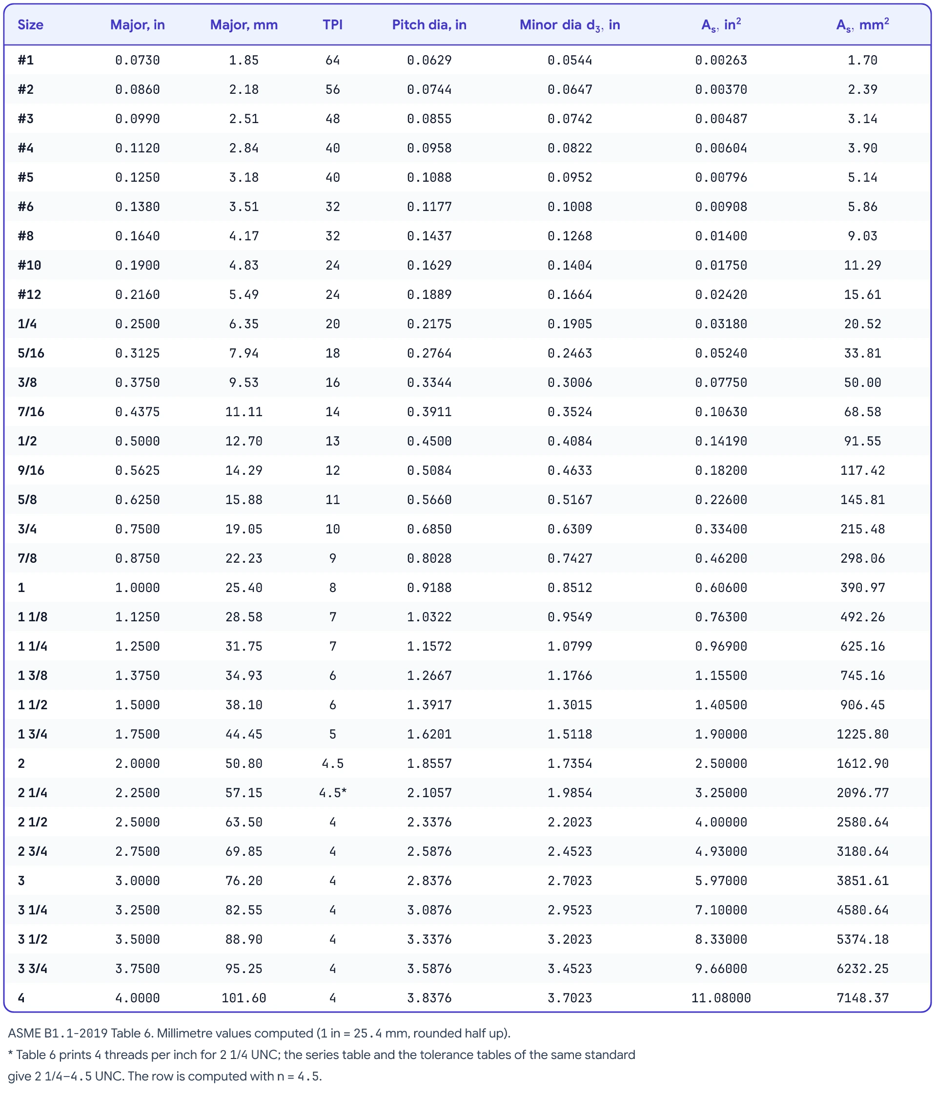
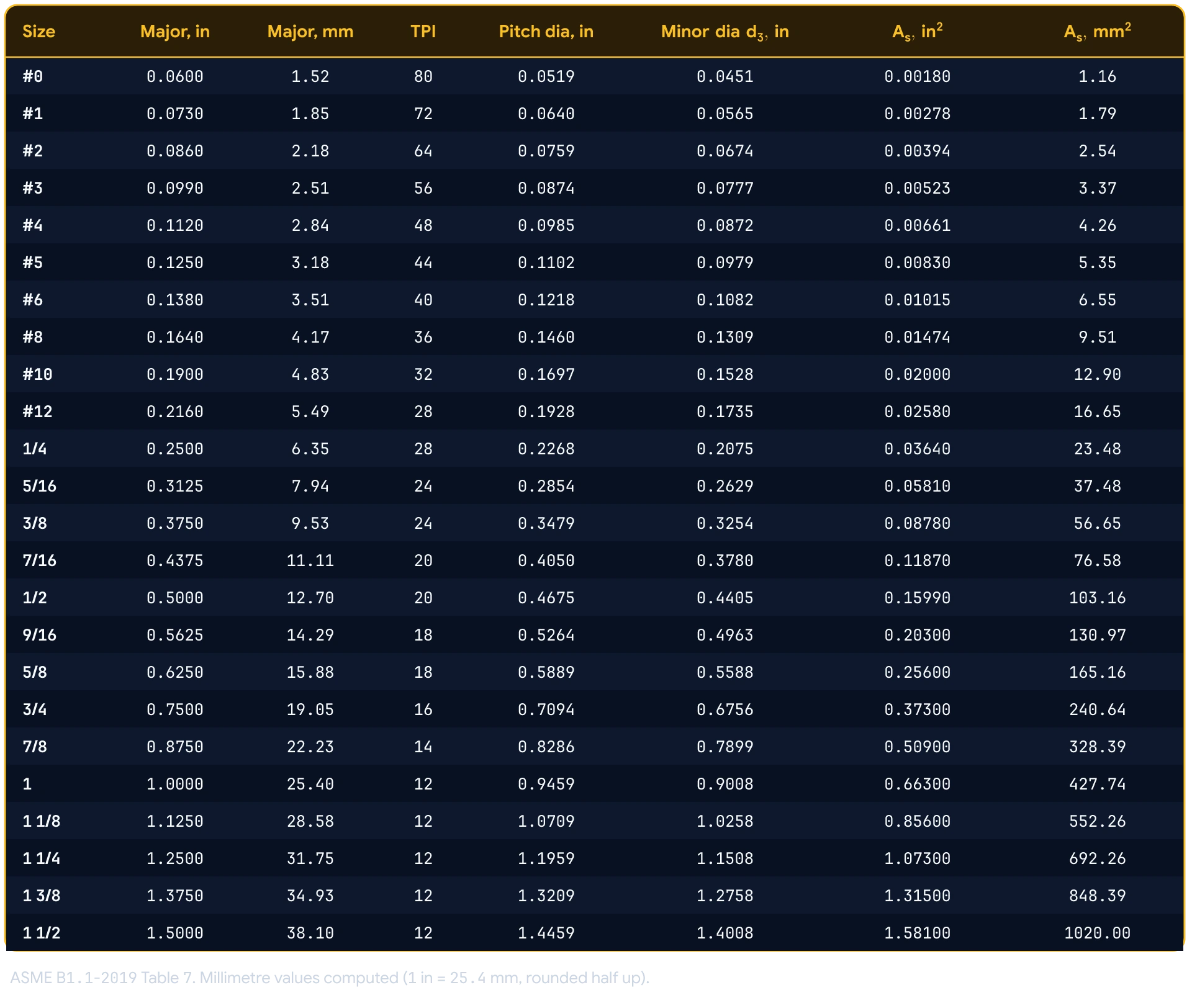
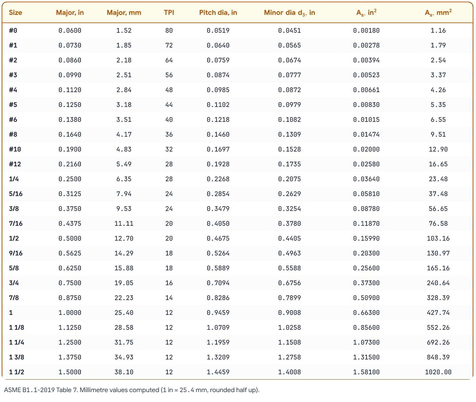
- Page 2. The unified coarse (UNC, #1 to 4 in) and fine (UNF, #0 to 1 1/2 in) series of ASME B1.1 Tables 6 and 7: major, pitch and minor diameter, threads per inch and tensile stress area in square inches and square millimetres, with the inch thread formulas.
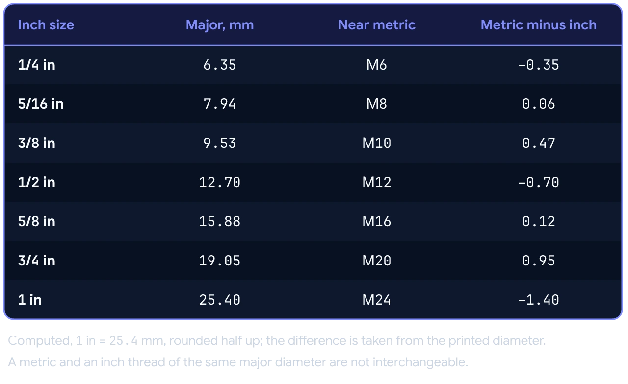
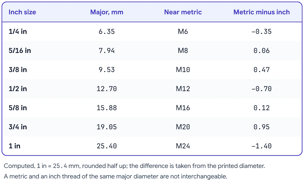
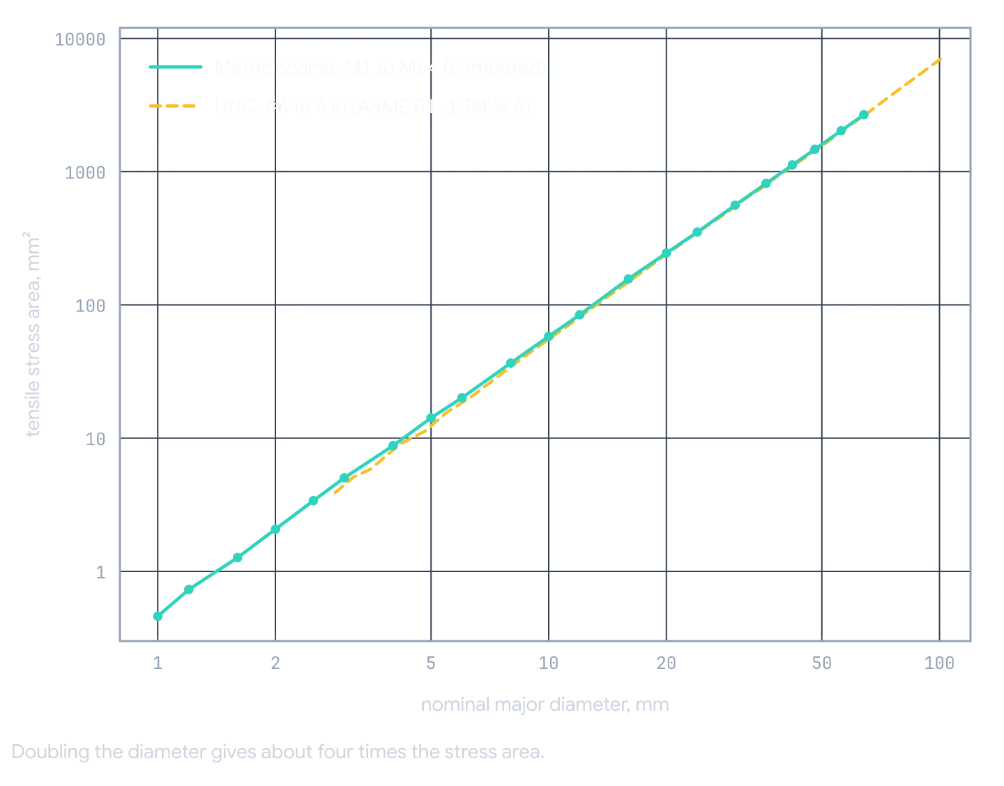
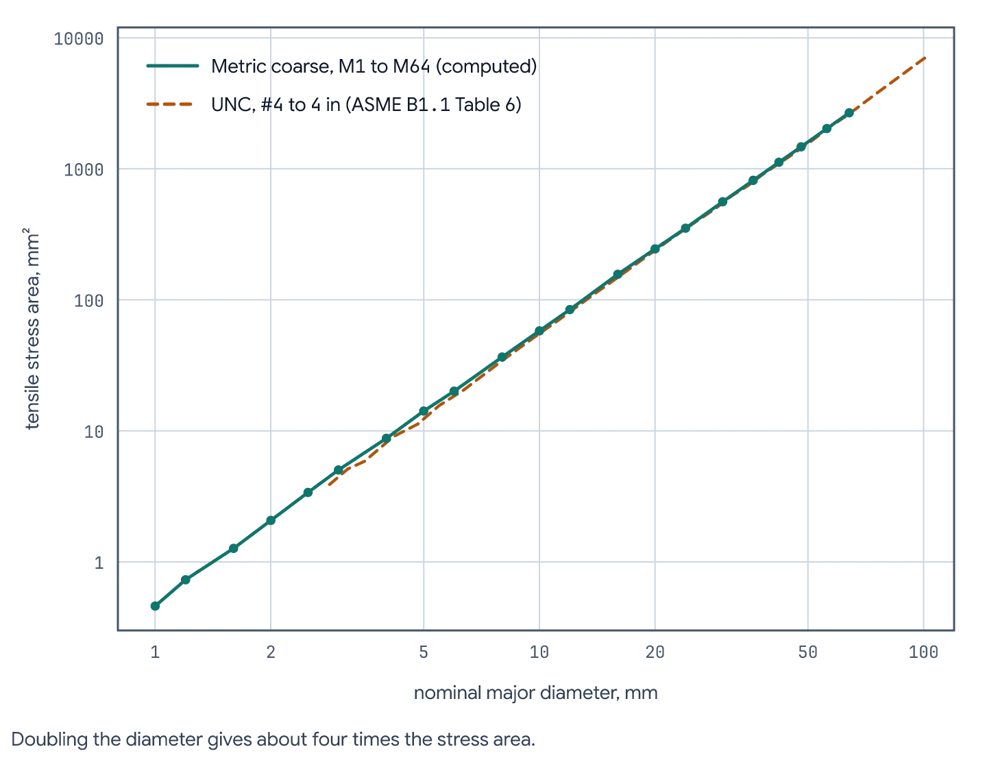
- Page 3. How a thread is written, the pitch and threads-per-inch conversion, the tensile load of a thread, seven inch sizes against the nearest metric thread, and a log-log plot of stress area against size.
Metric threads
The 60° basic profile fixes every diameter from the major diameter and the pitch :
Unified inch threads
How a thread is written
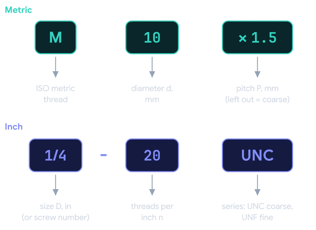
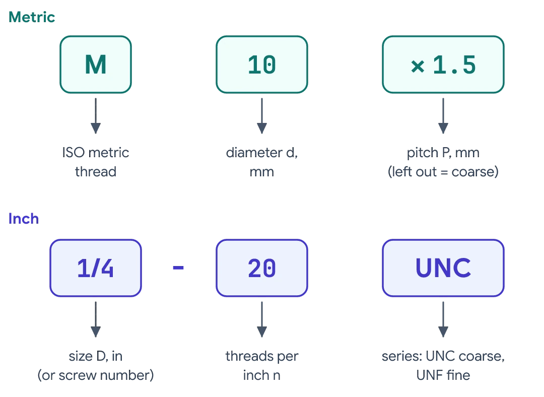
Coarse or fine, and how much load
The load a thread carries follows from the stress area and the stress of the bolt class:
At an assumed stress of 100 MPa an M10 gives 5.80 kN and a 1/4–20 UNC () gives 2.05 kN. Take the stress from the property class of the bolt: ISO 898-1 for metric bolts, SAE J429 or ASTM grades for inch bolts.
Where the numbers come from
The pitches come from ISO 261:1998 Table 2 and the inch dimensions from ASME B1.1-2019 Tables 6 and 7, read by script from the standards. The metric pitch and minor diameters, stress areas, tap drills and every inch-to-millimetre value are computed, and each computed value is labelled on the chart. After the PDF is built, a second script reads it back and compares every printed number with the data.
The chart is a reading aid. For a drawing, a contract or an inspection report, ISO 261, ISO 262, ISO 898-1 and ASME B1.1 are the authority. Second and third choice metric diameters (M14, M18, M22 and others) and sizes outside these tables are in the standards.
Related
- ISO 286 Limits and Fits Wall Chart: the size tolerances that go with a thread fit.
- Steel Pipe Dimensions Chart: the same method for pipe sizes and walls.
- Mechanical Design Data Handbook: reference tables for mechanical design.
Questions or a design you want reviewed? Get in touch.
The chart at a glance
Get the chart
About 61 KB PDF.
bolt-screw-size-chart.pdf
Questions, answered
Is the chart free?
Yes. Enter your name and email and the download link appears at once.
Which sizes are not on the chart?
The second and third choice metric diameters (M14, M18, M22 and others), metric sizes above M64, unified sizes above 4 in and the other thread series. Use ISO 261 or ASME B1.1 for those.
Can I rely on the numbers for a contract?
Use them to design and check. For contracts and inspection reports the standards ISO 261, ISO 898-1 and ASME B1.1 are the authority.
Share this engineering resource
Recommend this chart to colleagues.
More Tools
More Engineering Tools
ISO 286 Limits and Fits Wall Chart
A free two-page A3 wall chart for ISO 286 limits and fits: tolerance grades IT5 to IT12, the six hole-basis fits of ISO 286-1 and the limit deviations of 22 hole and shaft classes for 3 to 400 mm, read from the standard.
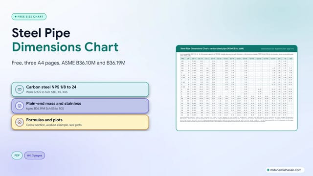
Steel Pipe Dimensions Chart
A free three-page A4 size chart for steel pipe: outside diameter, wall thickness and plain-end mass of carbon steel pipe NPS 1/8 to 24 by schedule (ASME B36.10M) and of stainless pipe (ASME B36.19M).