
Sheet Metal K-Factor and Bend Deduction Mathematics in Automated Design
How K-factor, bend allowance, setback and bend deduction fit together. Plain-language explanations, worked examples with checked numbers, a K-factor calibration method, and a tested calculator you can wire into an automated design flow.

Md Anamul Hasan
Project Manager & Mechanical Engineer
- July 12, 2026
- 21 min read
- 341 reads
- Updated November 2, 2026
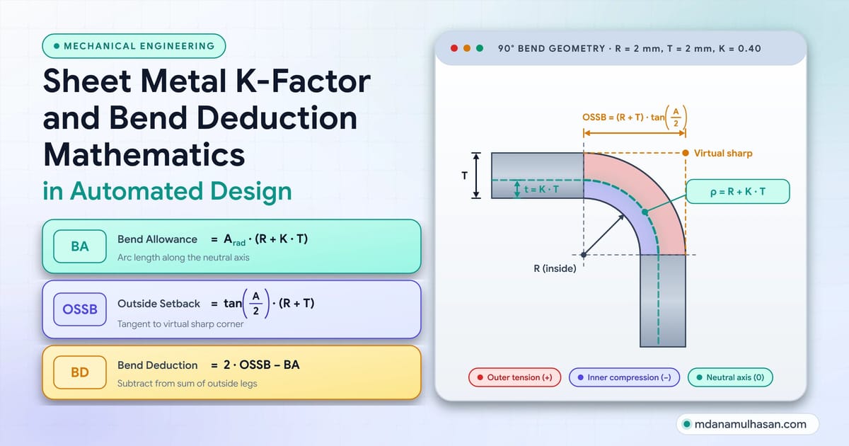
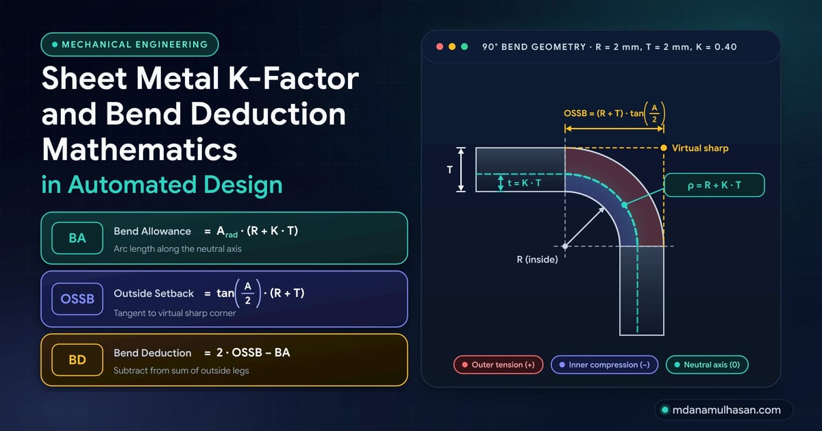
Flat length is arc length. Everything else in this article is bookkeeping around that fact.
A press brake turns a flat blank into a bent part. The CAD flat pattern has to predict the blank length before anyone cuts metal. If the prediction is off by 0.3 mm per bend, parts stop fitting, holes stop lining up and a team starts adding “shop fudge” numbers to drawings.
I work in mechanical design and CAD automation, with 9+ years of experience. Bend maths is where most sheet metal automation either becomes reliable or quietly breaks. This guide explains the maths in plain language, shows every step with numbers you can check, and points to a tested calculator you can put inside an automated flow.
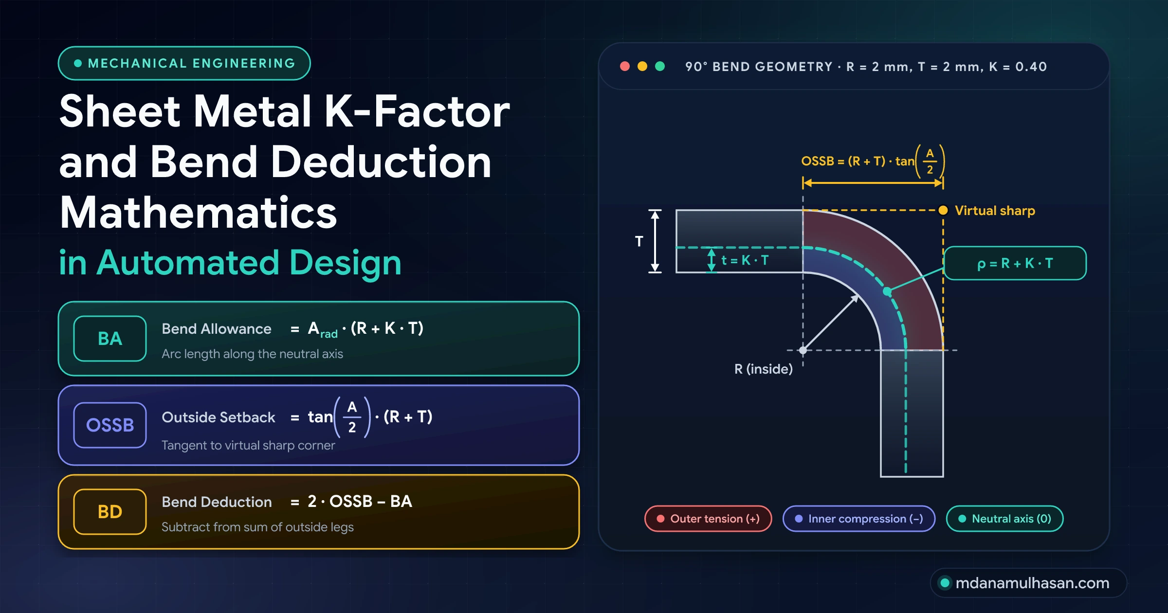
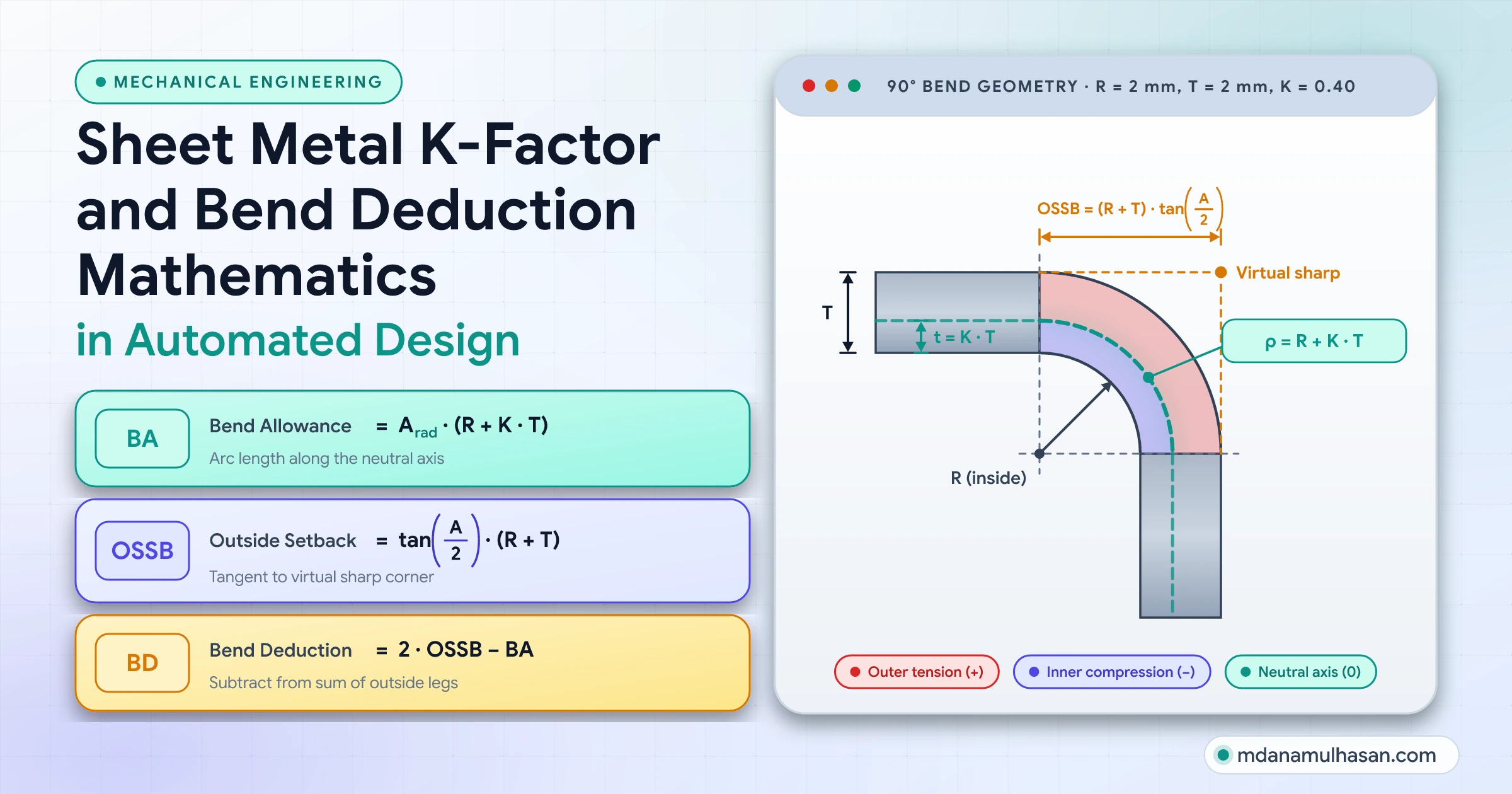
The one-minute version
K-factor (K) is where the neutral axis sits in the thickness, measured from the inside face, as a fraction of the thickness. It is a position, between 0 and 0.5 for conventional bends.
Bend allowance (BA) is the length of the neutral axis through the bend. It is the amount of flat blank the bend consumes.
Bend deduction (BD) is how much you subtract from the sum of the outside dimensions to get the flat length.
K sets BA. BA sets BD. BD sets the blank. If K is wrong, every number after it is wrong.
The three formulas you need, with as the bend angle (not the included angle):
Where is the inside bend radius, is the sheet thickness and is the outside setback. All lengths are in millimetres and is in degrees.
Terms you will see in this article
| Term | Plain meaning |
|---|---|
| Bend angle (A) | How far the flange is turned from flat. 0° is flat. 90° is a square corner. |
| Included angle | The angle between the two flanges after bending. Included angle = 180° − A. |
| Inside radius ® | Radius of the inner surface of the bend. |
| Thickness (T) | Sheet thickness. |
| Neutral axis | The layer inside the sheet whose length does not change during bending. |
| K-factor (K) | Neutral axis distance from the inside face, divided by T. |
| Bend allowance (BA) | Arc length of the neutral axis through the bend. |
| Virtual sharp | The point where the two flange faces would meet if the corner were sharp. |
| Outside setback (OSSB) | Distance from the virtual sharp (outside) to where the bend starts on the flat. |
| Inside setback (ISSB) | Same idea, measured from the inside virtual sharp. |
| Bend deduction (BD) | Amount subtracted from the outside dimensions to get the flat length. |
| Y-factor | Another way to write K for some CAD systems: . |
Why a bend needs maths at all
A flat strip has one length. A bent part has two flanges and a curve. If you add the two outside flange lengths, you count the corner twice. The material that forms the curve is shorter than the two outside lengths suggest, but longer than a sharp corner would suggest. You need a rule that says exactly how much.
That rule is the neutral axis.
The neutral axis, explained simply
When you bend a strip, the inside face gets squeezed and the outside face gets stretched. Somewhere between them there is a layer that is neither squeezed nor stretched. Its length stays the same as it was when flat. That layer is the neutral axis.
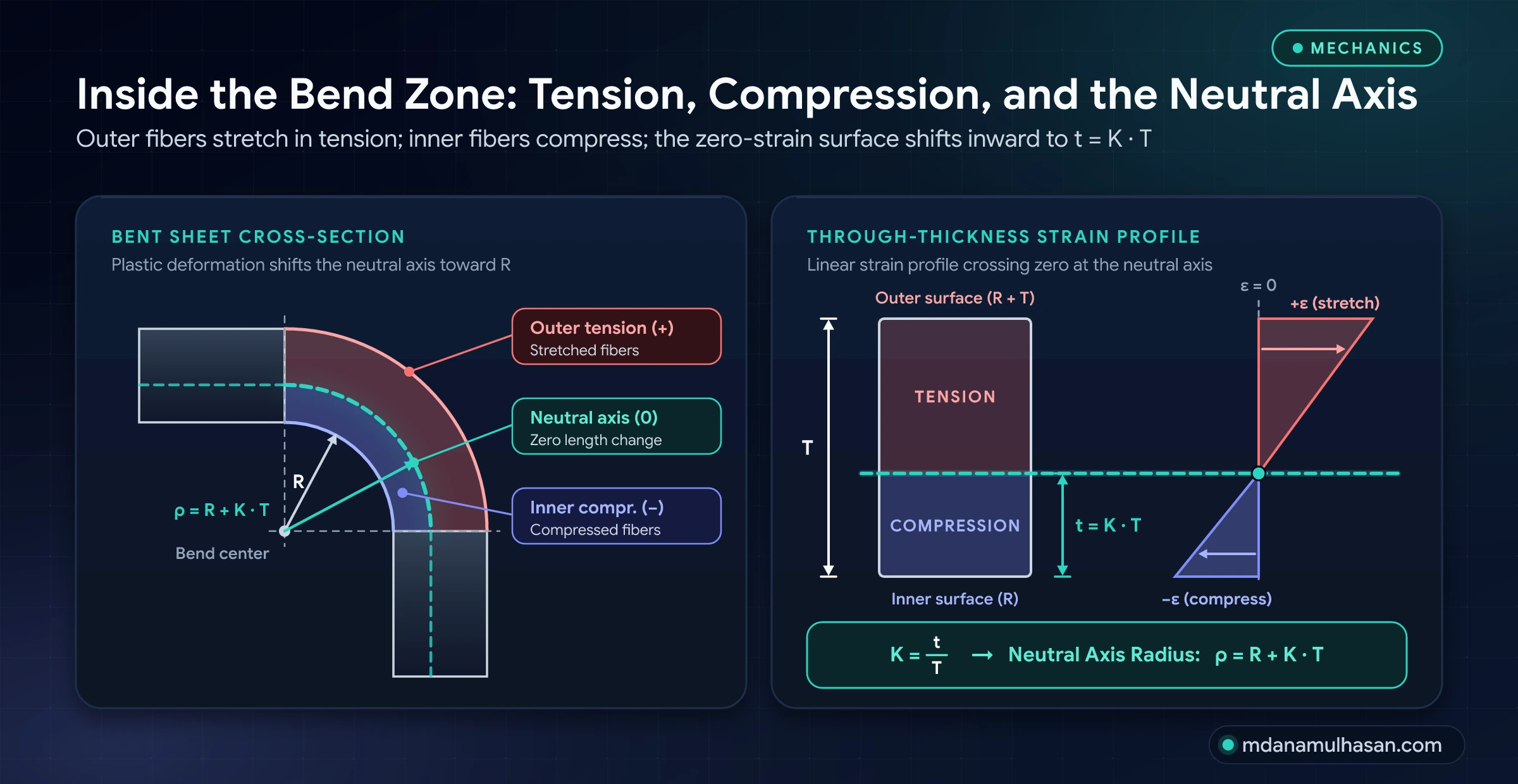
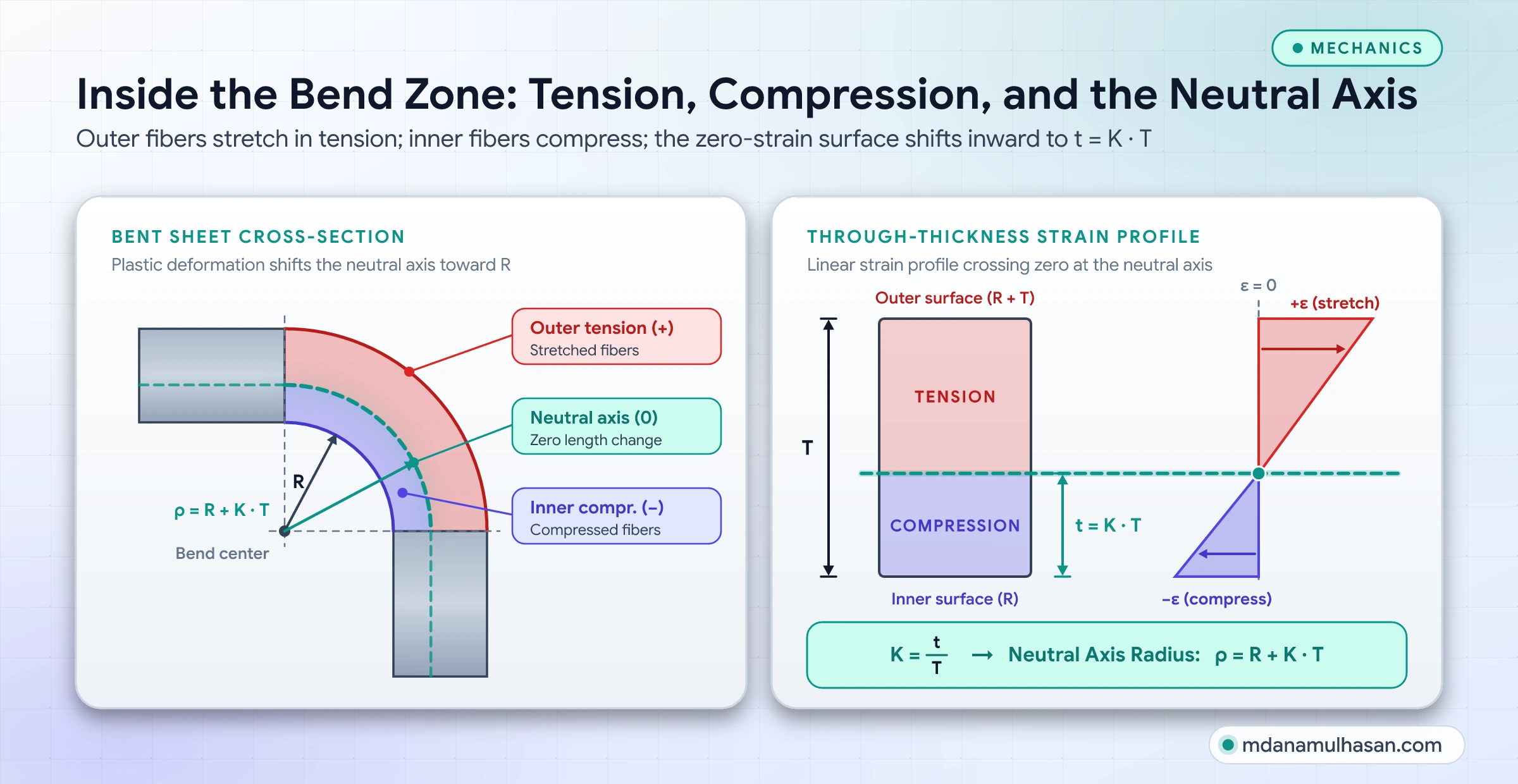
The strain diagram on the right is the key picture. Strain changes in a straight line through the thickness. It is zero at the neutral axis, negative (compression) toward the inside and positive (tension) toward the outside.
If the neutral axis sat exactly in the middle, the inside and outside would be strained equally. In real bends the neutral axis shifts toward the inside. The outer half stretches more than the inner half compresses. That shift is what K measures.
K-factor: a position, not a material constant
is the distance from the inside face to the neutral axis. is the full thickness.
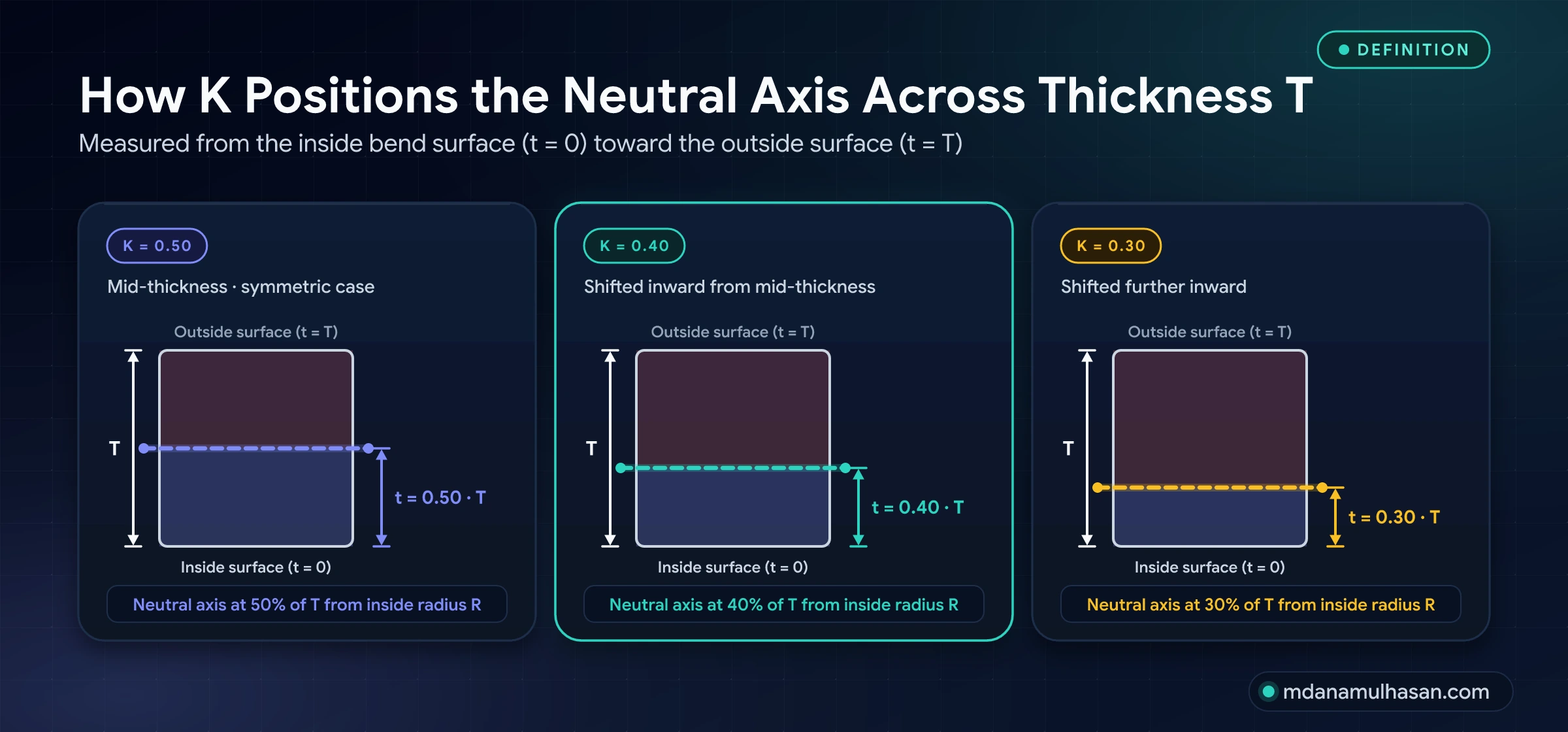
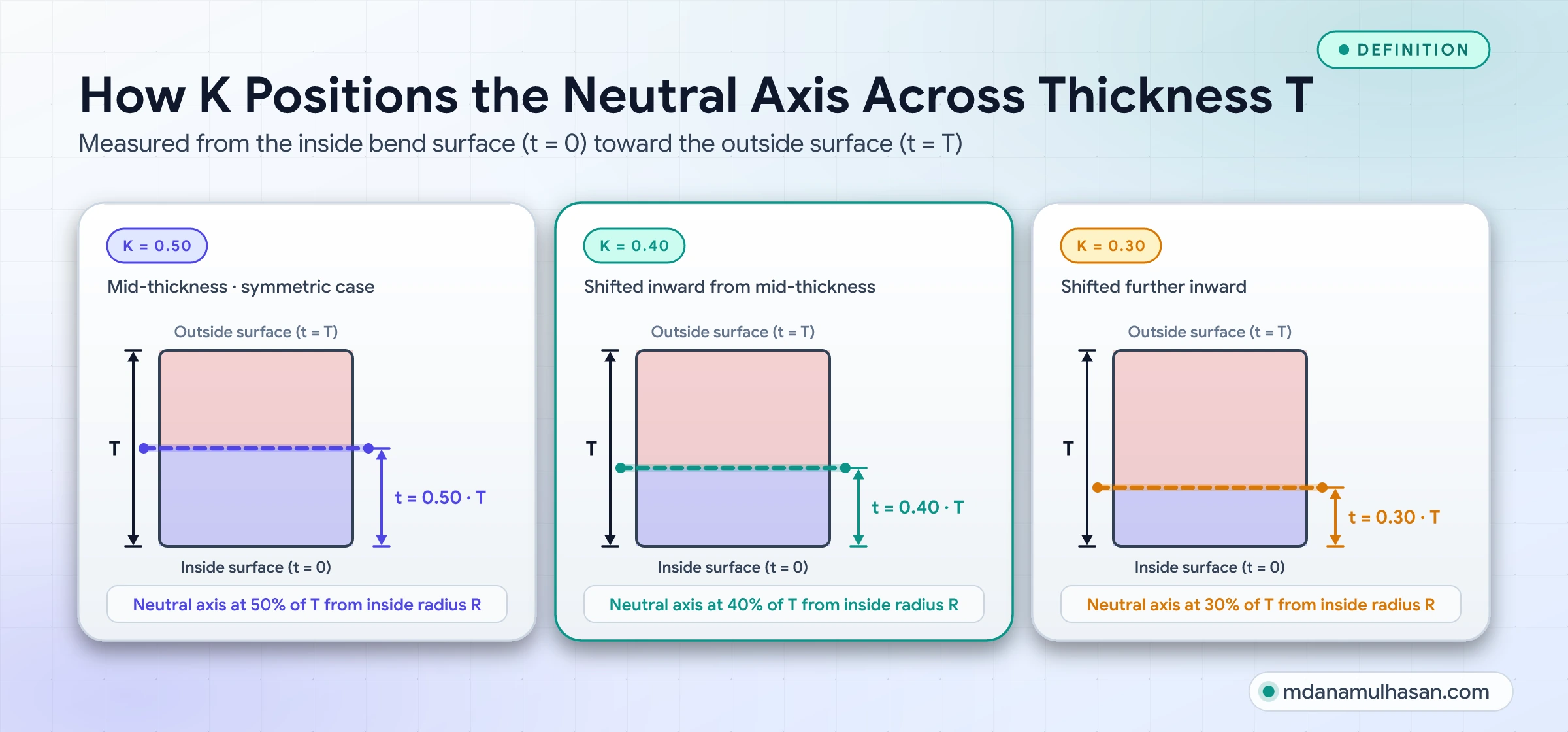
Three things follow from the definition.
- K is dimensionless. It is a fraction of thickness.
- K = 0.5 means the neutral axis is at mid-thickness. That is the symmetric case.
- For conventional bending, K lies between 0 and 0.5. A value above 0.5 in a calibration usually means a measurement or input error. The free bend calculator rejects it for that reason. That limit is a design choice. Relax it only if you have evidence for your process.
What moves K
K is empirical. It depends on the material, the thickness, the inside radius, and how the part is formed. These effects are well established in practice, though the exact values are not universal.
| Factor | Effect on K |
|---|---|
| Radius to thickness ratio (R/T) | Tighter bends push the neutral axis toward the inside, so K drops. Gentle bends approach 0.5. |
| Material and temper | Different yield behaviour and work hardening shift the neutral axis. |
| Forming method | Air bending, bottoming and coining deform the sheet differently. |
| Tooling | Die opening and punch geometry change the actual inside radius. |
| Grain direction | Bending along or across the rolling direction behaves differently in many materials. |
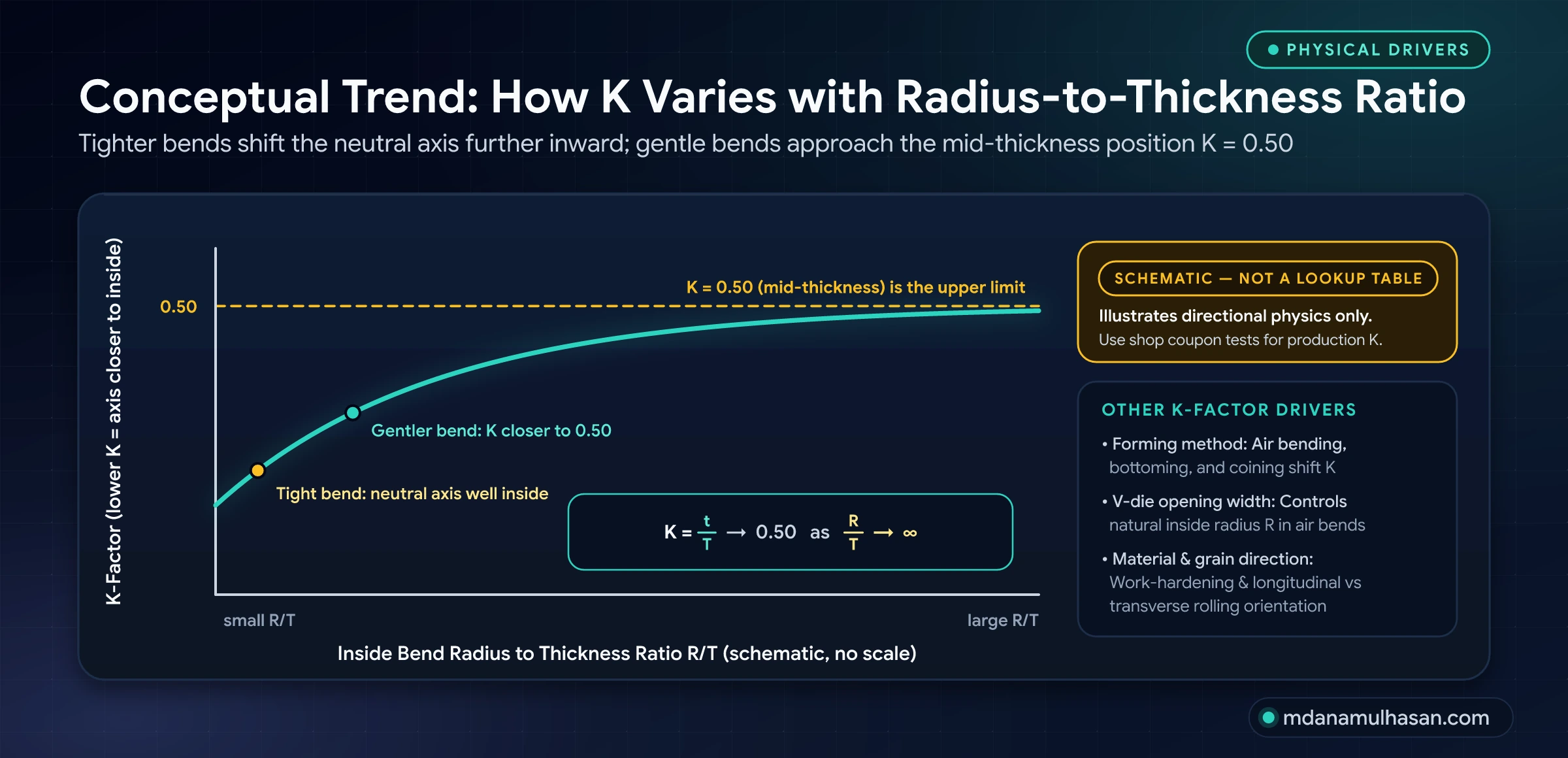
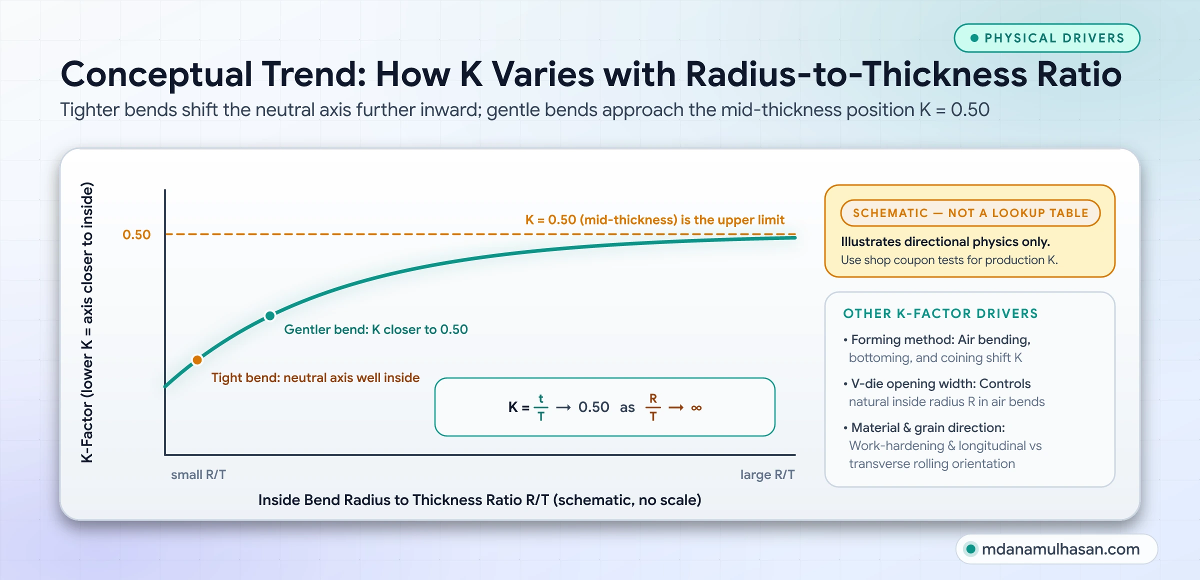
Verify before you rely on it. Published K-factor tables differ between sources, and none of them know your brake and your coil. Start from a table if you must, then calibrate (see below).
Bend allowance: the arc length of the neutral axis
A bend is an arc. Its length is radius times angle in radians. The relevant radius is the radius of the neutral axis, which is the inside radius plus the neutral axis distance:
That is all BA is. For a 90° bend it simplifies to:
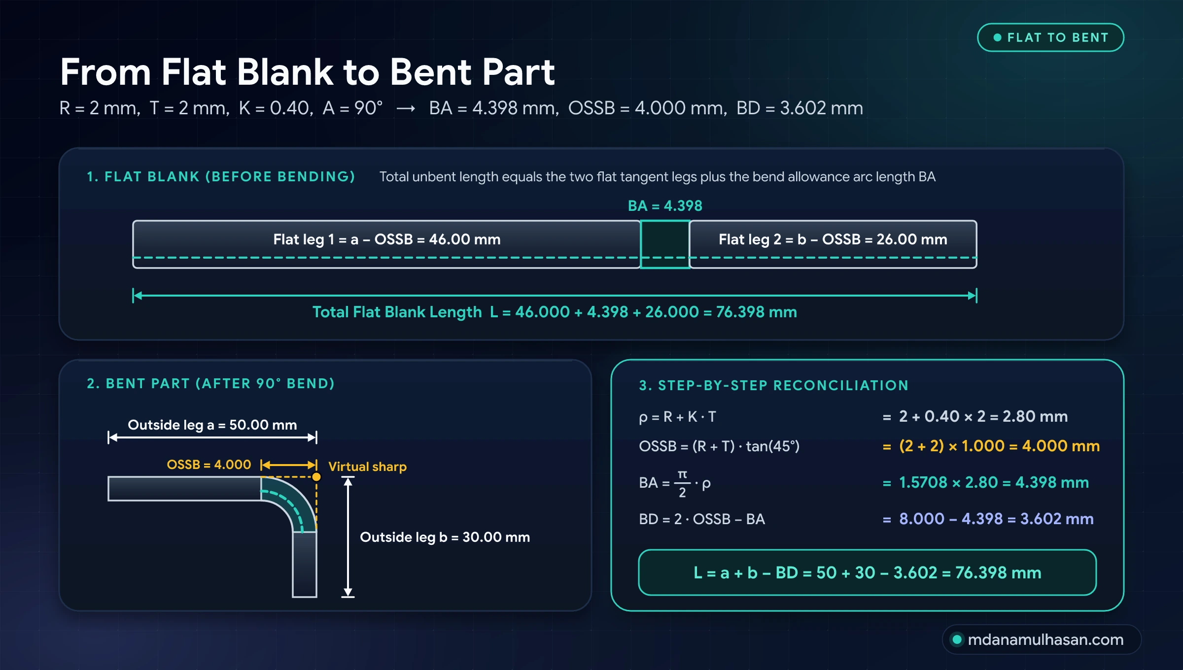
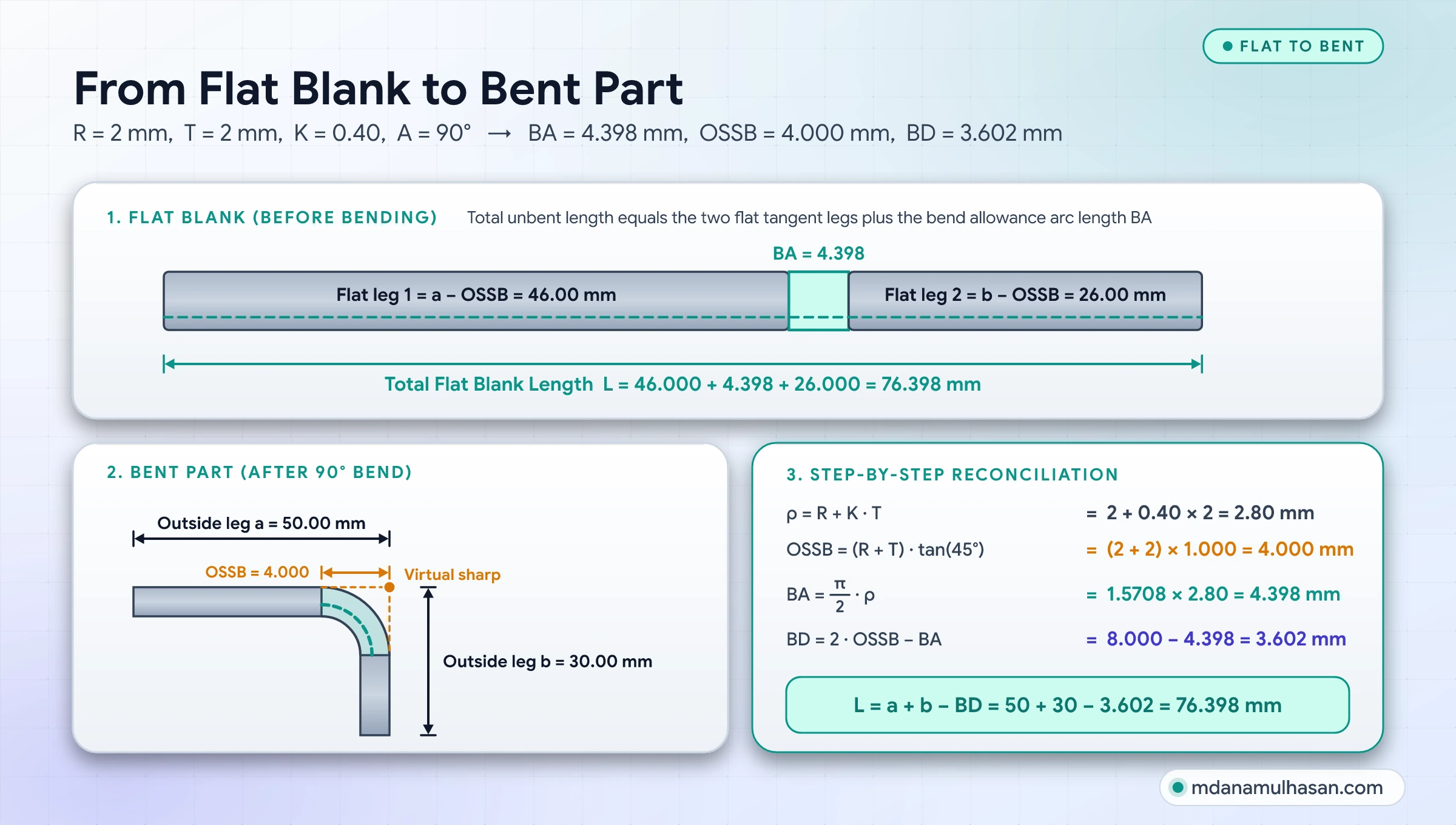
Sanity check. With , , : mm and mm. The bend uses 4.398 mm of flat blank.
Setback and bend deduction
BA tells you how much blank the curve uses. It does not tell you how to use your drawing dimensions. Drawings usually dimension to the outside, to the virtual sharp. For that you need setback.
Outside setback is the distance from the virtual sharp back to the point where the flat ends and the curve begins:
For a 90° bend, , so .
Bend deduction follows from geometry. Two outside legs, measured to the virtual sharp, each include one OSSB that is not really flat material. Together they over-count by . The curve that actually exists is long. So:
Why BD is always positive
For small angles, , so:
Since , BD is positive. Check: , , gives mm. The calculator’s self-test confirms this limit. This is a useful automated check: a negative BD means a bad input.
Always use the bend angle
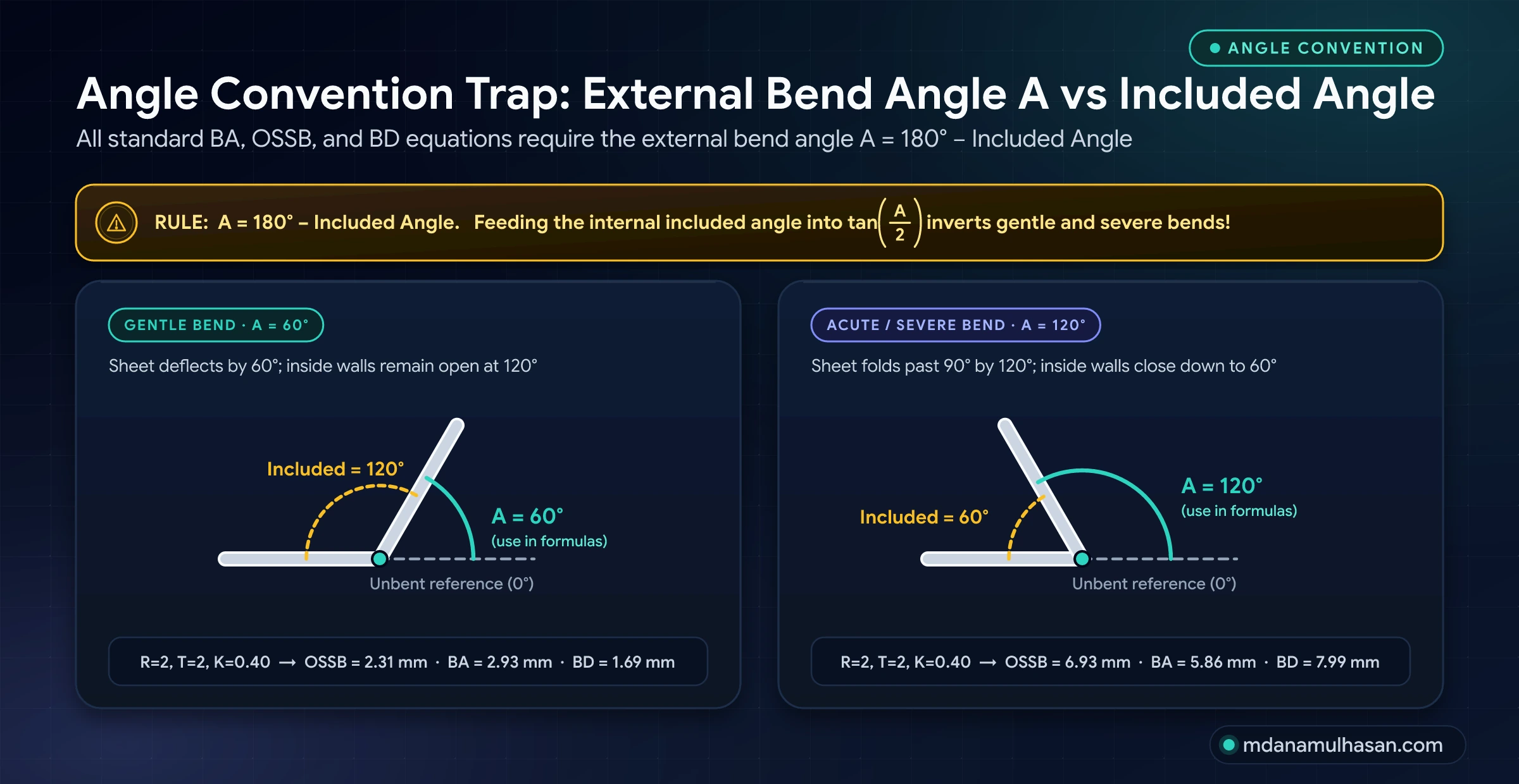
This is the most common input error in handwritten and spreadsheet calculators. A part drawn with a 60° included angle has a 120° bend angle. If you feed 60° into the formulas, the answer is wrong by several millimetres, and the error looks plausible.
Setback factors by angle
For mm and mm, mm:
| Bend angle | (mm) | |
|---|---|---|
| 30° | 0.2679 | 1.072 |
| 45° | 0.4142 | 1.657 |
| 60° | 0.5774 | 2.309 |
| 90° | 1.0000 | 4.000 |
| 120° | 1.7321 | 6.928 |
| 135° | 2.4142 | 9.657 |
| 150° | 3.7321 | 14.928 |
Setback grows fast as the bend gets more severe. At 150° it is almost four times .
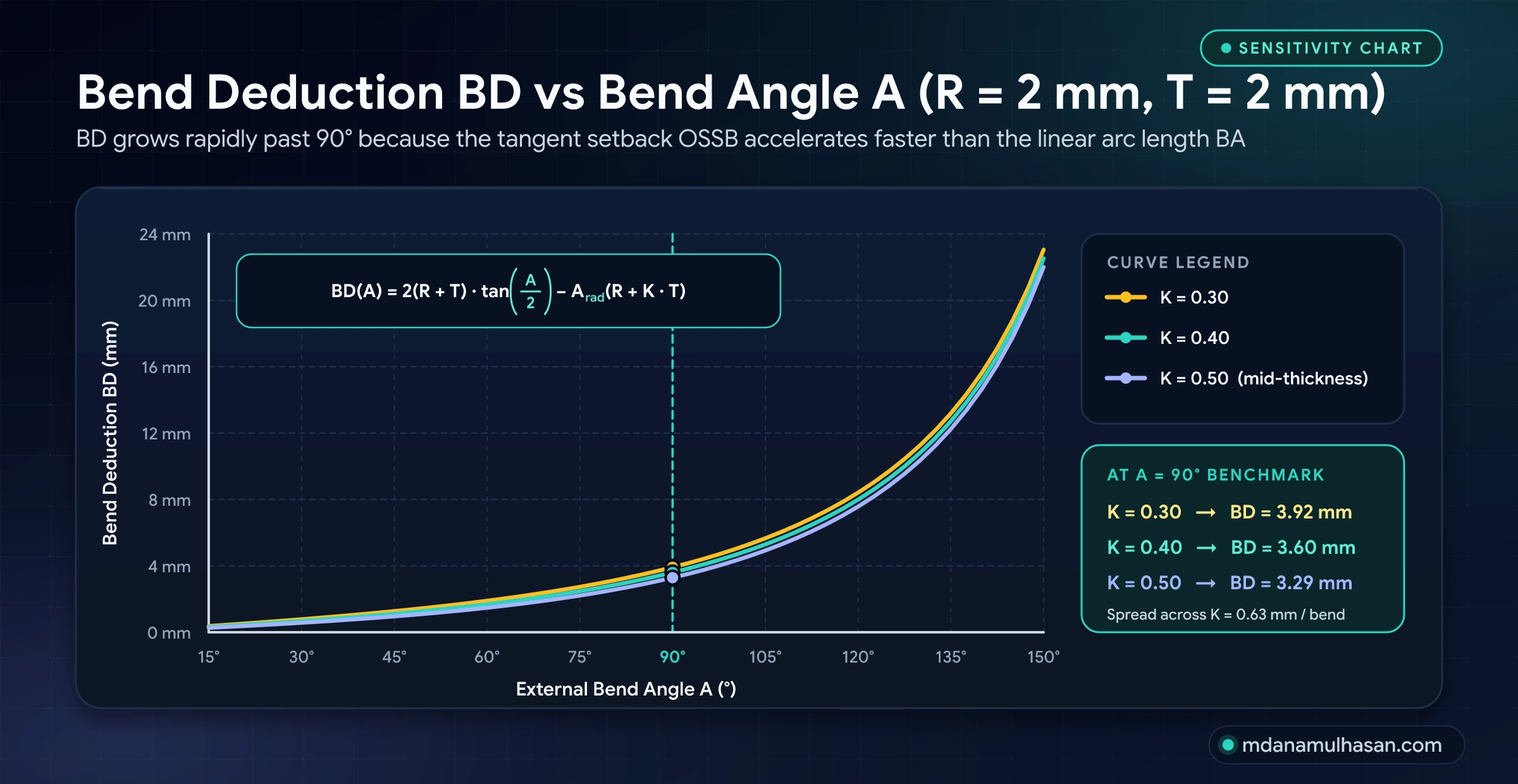
How BD changes with K and angle
For , , :
| K | BA (mm) | BD (mm) |
|---|---|---|
| 0.30 | 4.084 | 3.916 |
| 0.35 | 4.241 | 3.759 |
| 0.40 | 4.398 | 3.602 |
| 0.45 | 4.555 | 3.445 |
| 0.50 | 4.712 | 3.288 |
Higher K means a longer neutral axis arc, so more blank is consumed by the bend and the deduction shrinks.
Three ways to dimension a bend
The same bend can be dimensioned three ways. All three give the same flat length. The risk is mixing them.
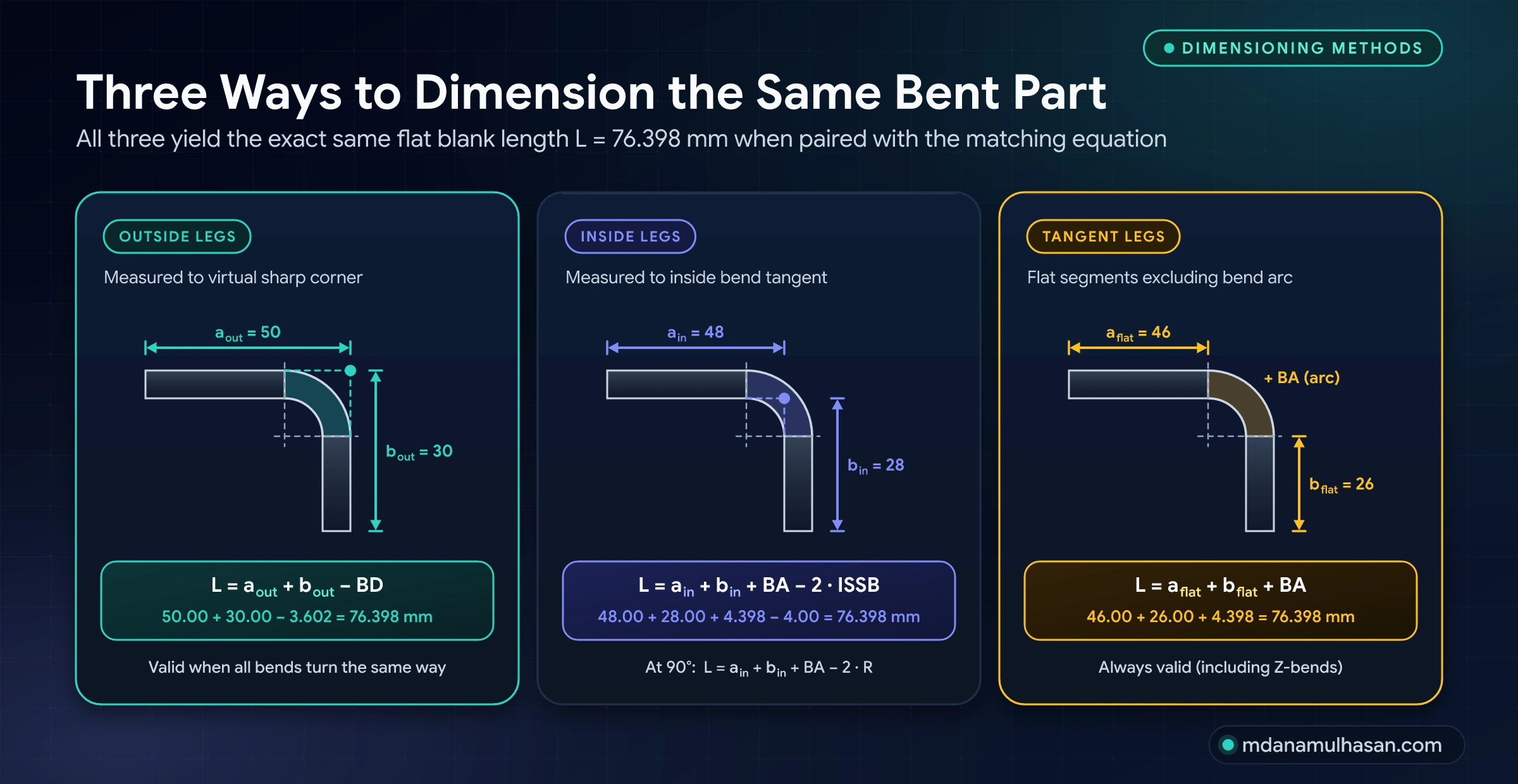
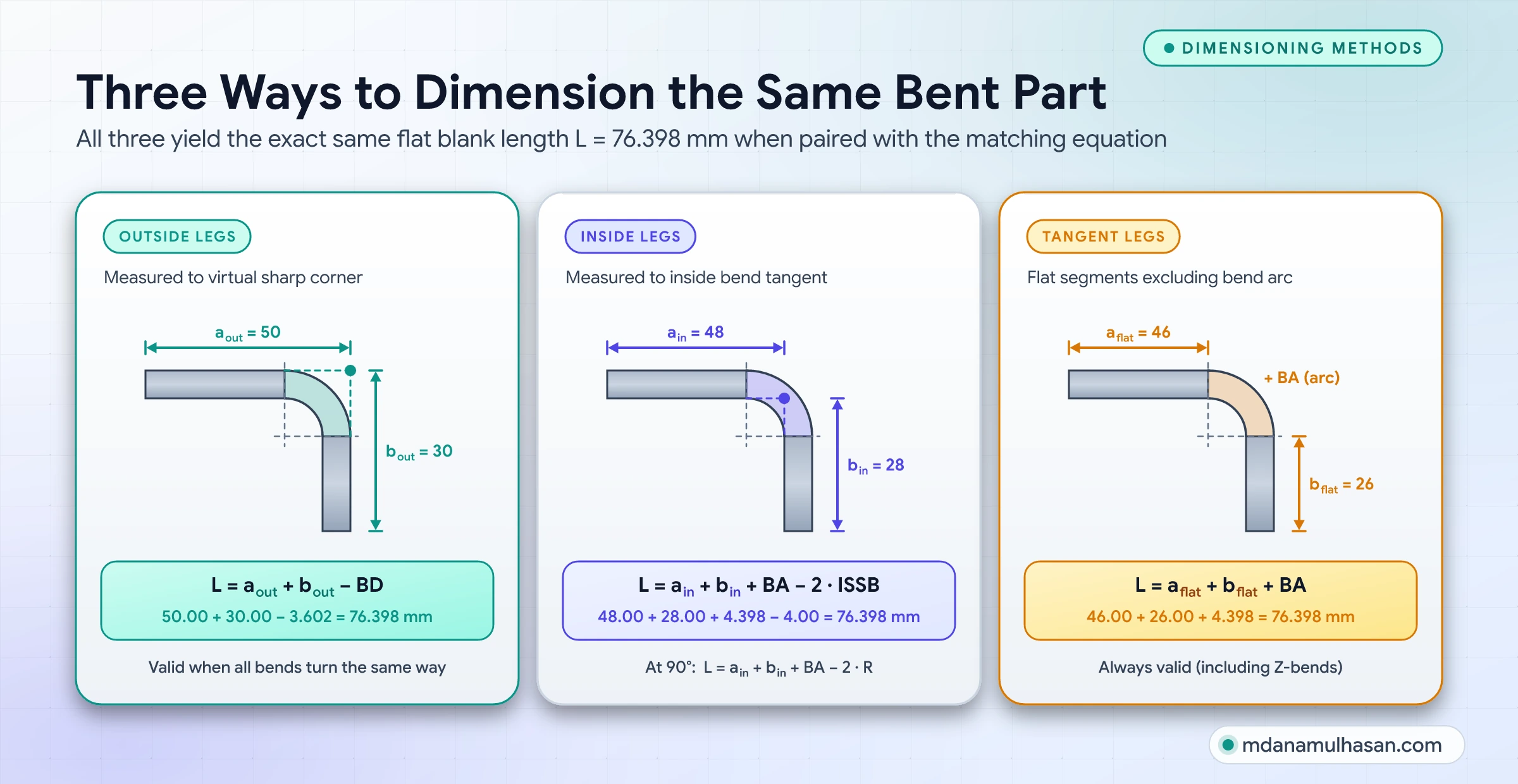
| Method | Dimensions measured to | Flat length |
|---|---|---|
| Outside | Outside virtual sharp | |
| Inside | Inside virtual sharp | |
| Flat (tangent) | Where the straight part ends |
With .
Notes:
- The outside and inside formulas assume every bend turns the same way (L, U and hat sections). For Z-bends and joggles, use the tangent method. It is always valid.
- For automation, store the tangent lengths internally and convert to outside or inside dimensions only for display. That removes a whole class of convention errors.
Worked examples
All numbers below come from the free Sheet Metal Bend Calculator, which has a self-test.
Example 1: single 90° bend
Given , , , , outside legs 50 and 30 mm.
- mm
- mm
- mm
- mm
Cross-check by the tangent method. Flat legs are mm and mm. Then mm. Same answer. Cross-check by the inside method with inside legs mm and mm: mm, so mm. Same answer.
Example 2: U-channel with two bends
Given , , both bends , (assumed for this example), outside legs 25, 40 and 25 mm.
- mm
- mm
- mm
- mm
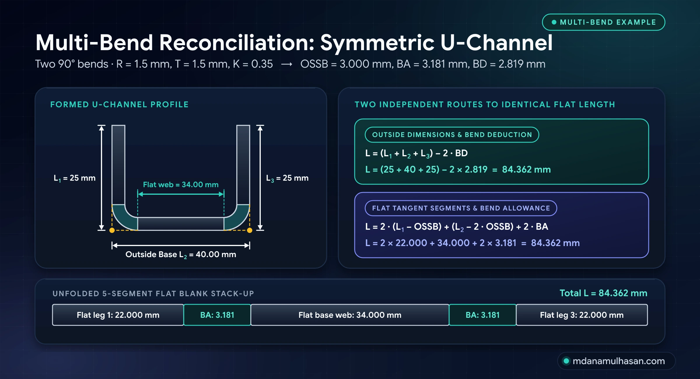
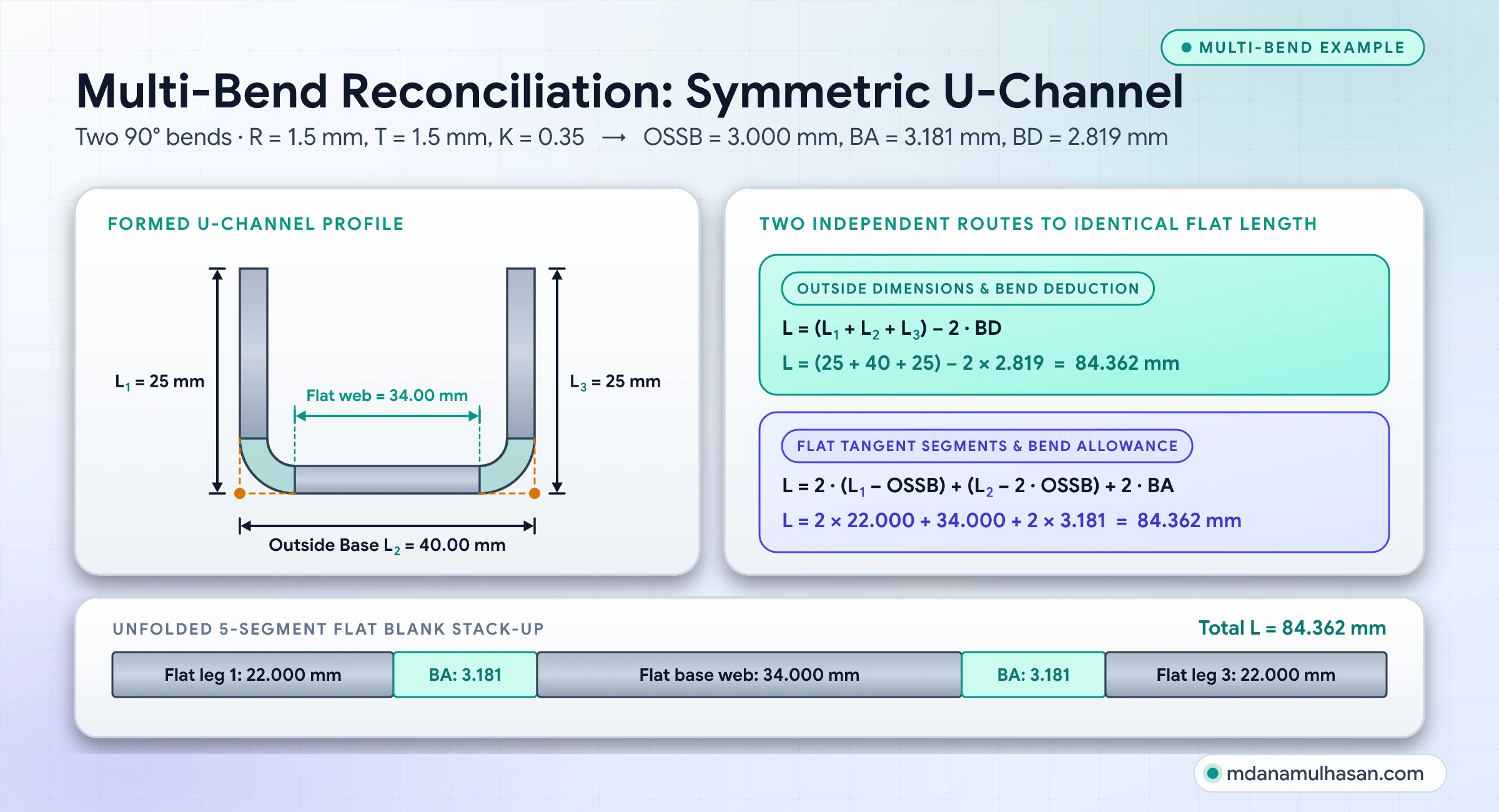
Two bends mean two copies of any K error. That is why a small K error is not a small length error on multi-bend parts.
Example 3: obtuse bend
Bend angle (so the included angle is 60°), , , , outside legs 40 and 40 mm.
- mm
- mm
- mm
- mm
Notice that BD is larger than for the 90° bend, even with a larger radius. The setback dominates.
Calibrating K from a test bend
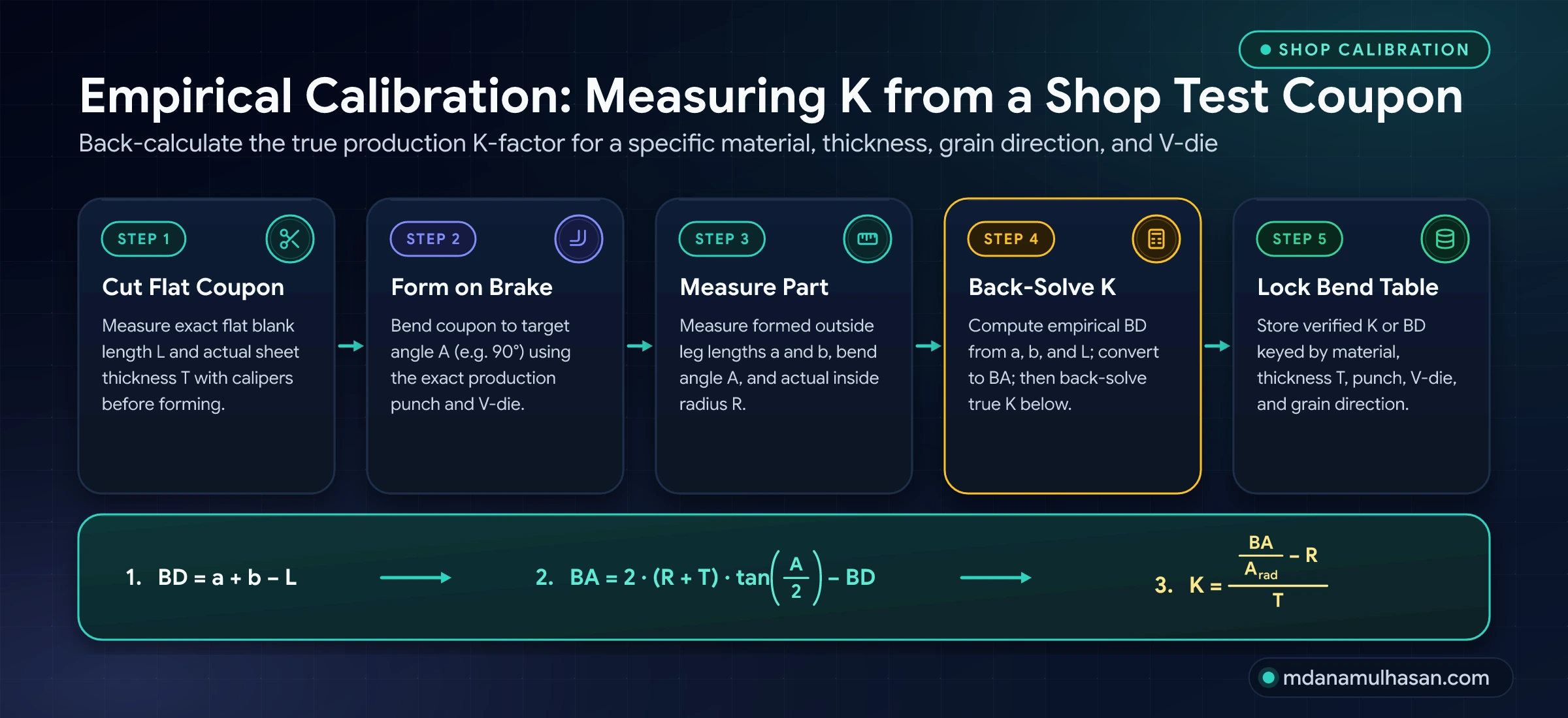
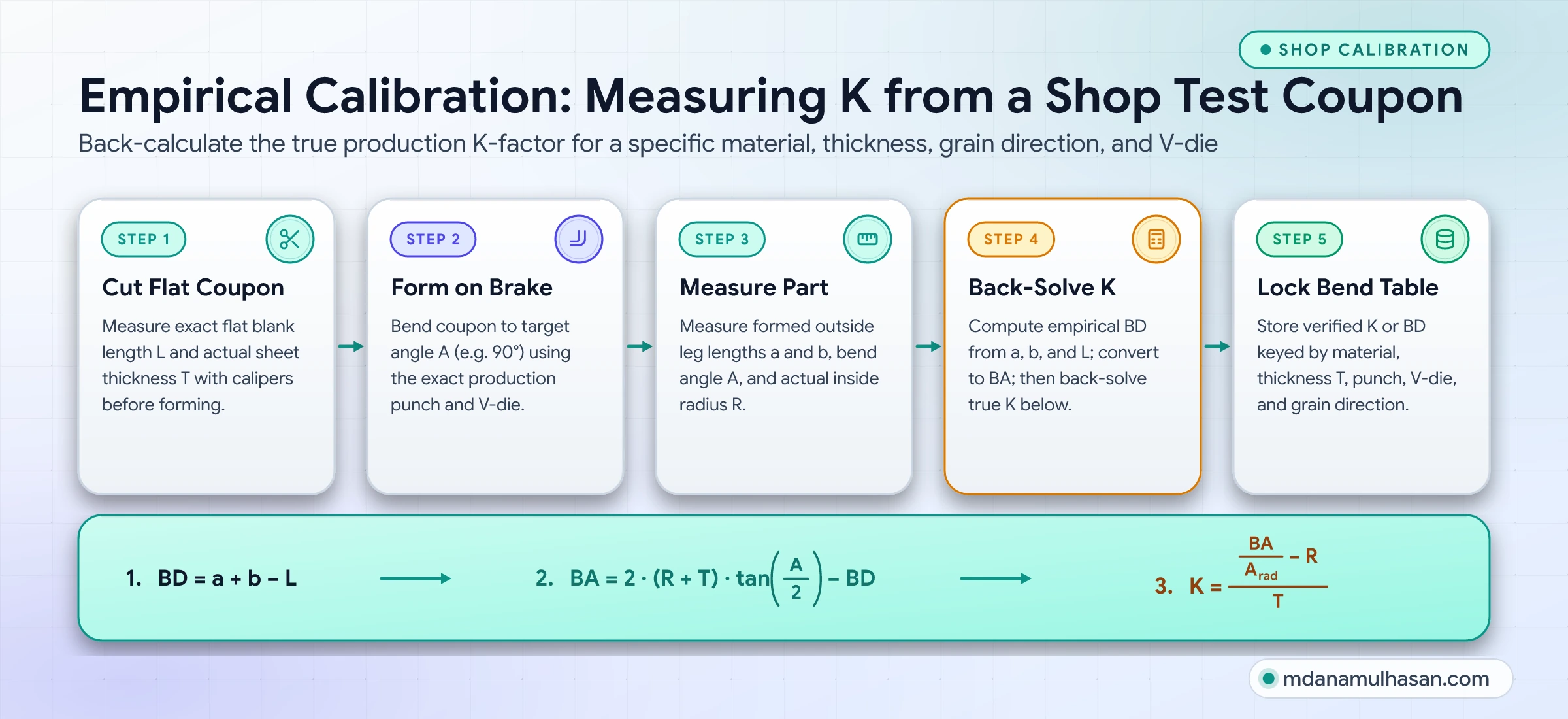
A table value is a guess. A calibration is a measurement. The method is short.
Procedure
- Cut 3 to 5 blanks of known length , from the same sheet, with the same grain direction.
- Bend each one on the production brake with the production tooling and process.
- Measure both outside legs, and , to the virtual sharp. Use calipers and a consistent method.
- Compute BD, then BA, then K:
- Average the results and store K against material, thickness, radius, tooling and process.
Use the actual inside radius. In air bending the radius is set by the die opening and the material, not by the punch nose. Get that figure from your tooling supplier or measure it. A wrong R gives a wrong K.
Example 4: a calibration
Given , , , blank mm. After bending, both outside legs measure 52.75 mm.
- mm
- mm
(The exact calculator output is 0.3793, because 52.75 is the rounded caliper reading.)
How sensitive is this? If each leg reads 0.05 mm higher, K comes out at 0.358. If each reads 0.05 mm lower, K is 0.401. A 0.1 mm combined error moves K by about 0.02. That is why you average several coupons and why the measurement method must be consistent.
What a K error costs
A K error changes BA by :
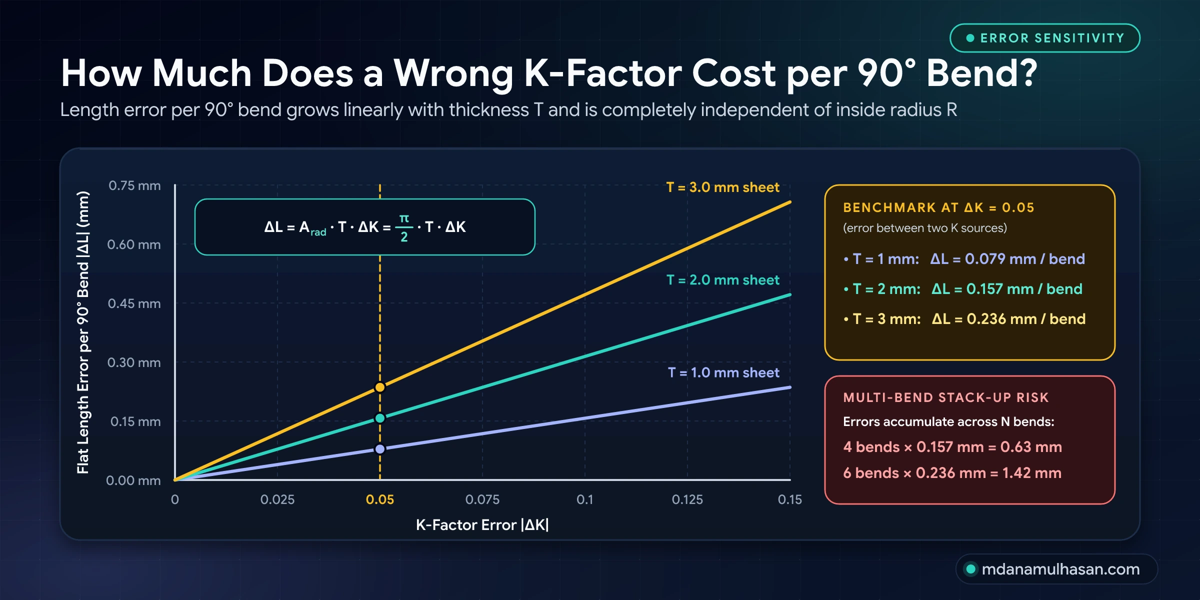
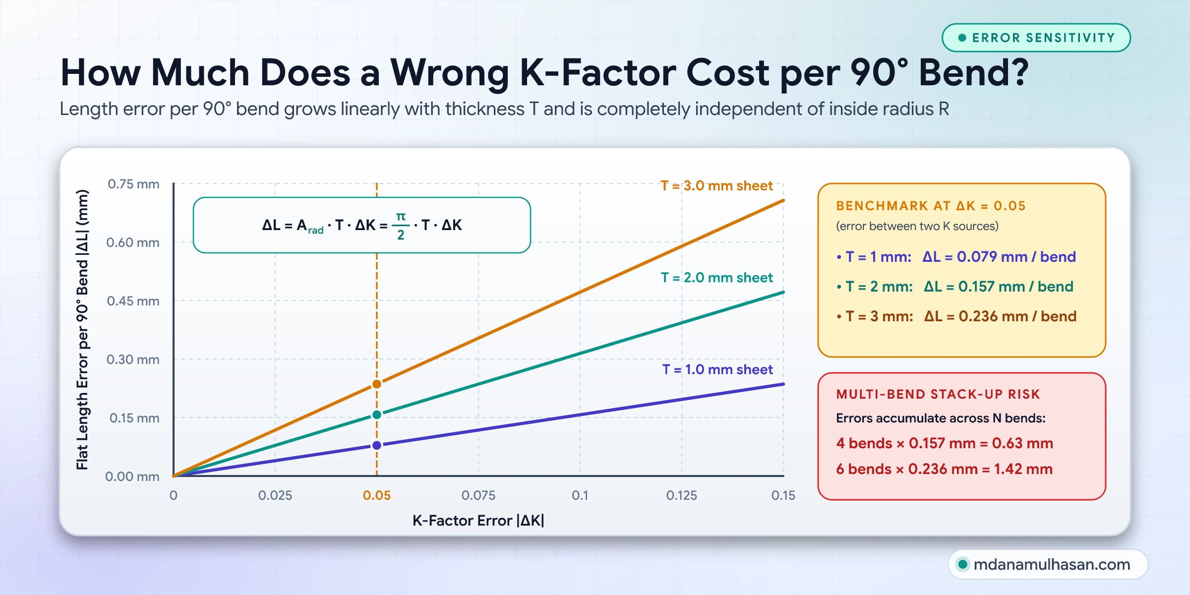
For a 90° bend and :
| Thickness T | Length error per bend |
|---|---|
| 1 mm | 0.079 mm |
| 2 mm | 0.157 mm |
| 3 mm | 0.236 mm |
Multiply by the number of bends. A part with six bends and mm, using a K that is 0.05 too far from reality, accumulates up to about 1.4 mm of length error if the errors stack in the same direction. Whether that matters depends on your tolerance.
Putting the maths into an automated flow
The calculator does not replace the CAD flat pattern. It audits it. The CAD system owns the geometry. The calculator owns an independent answer that you can compare against.
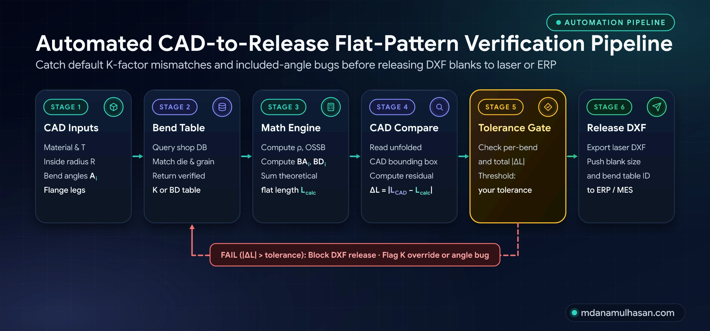
What to automate
| Step | Automation |
|---|---|
| Inputs | Read thickness, inside radius, bend angle and material from the model. |
| K lookup | Query a table keyed by material, thickness, radius and tooling. |
| Calculate | BA, OSSB, BD and flat length per bend. |
| Compare | Read the CAD flat pattern length and compare. |
| Gate | Pass if the difference is within your tolerance. Otherwise stop. |
| Release | Export DXF, CNC data and drawing only after the gate passes. |
CAD systems such as SolidWorks let you choose how bends are calculated, for example by K-factor, bend allowance, bend deduction or a bend table. The exact options and names depend on your version, so check your own documentation. What matters for automation is that the same K is used by the CAD model and by the calculator. Different K sources in two places is the most common reason an audit fails.
A bend table keyed for lookup
Store K in a table, not in people’s heads. Suggested columns:
| Column | Example | Notes |
|---|---|---|
| material | Example-Steel-A |
Use your internal material code. |
| thickness_mm | 2.0 |
Nominal thickness. |
| inside_radius_mm | 2.0 |
The actual formed radius. |
| tooling_id | TOOL-001 |
Punch and die set. |
| process | air |
air, bottoming, coining. |
| k_factor | from calibration | Measured, not copied. |
| n_coupons | from calibration | How many coupons averaged. |
| calibrated_on | date | When it was measured. |
Add a calibration date. K can drift with tooling wear, coil changes and process changes.
The calculator
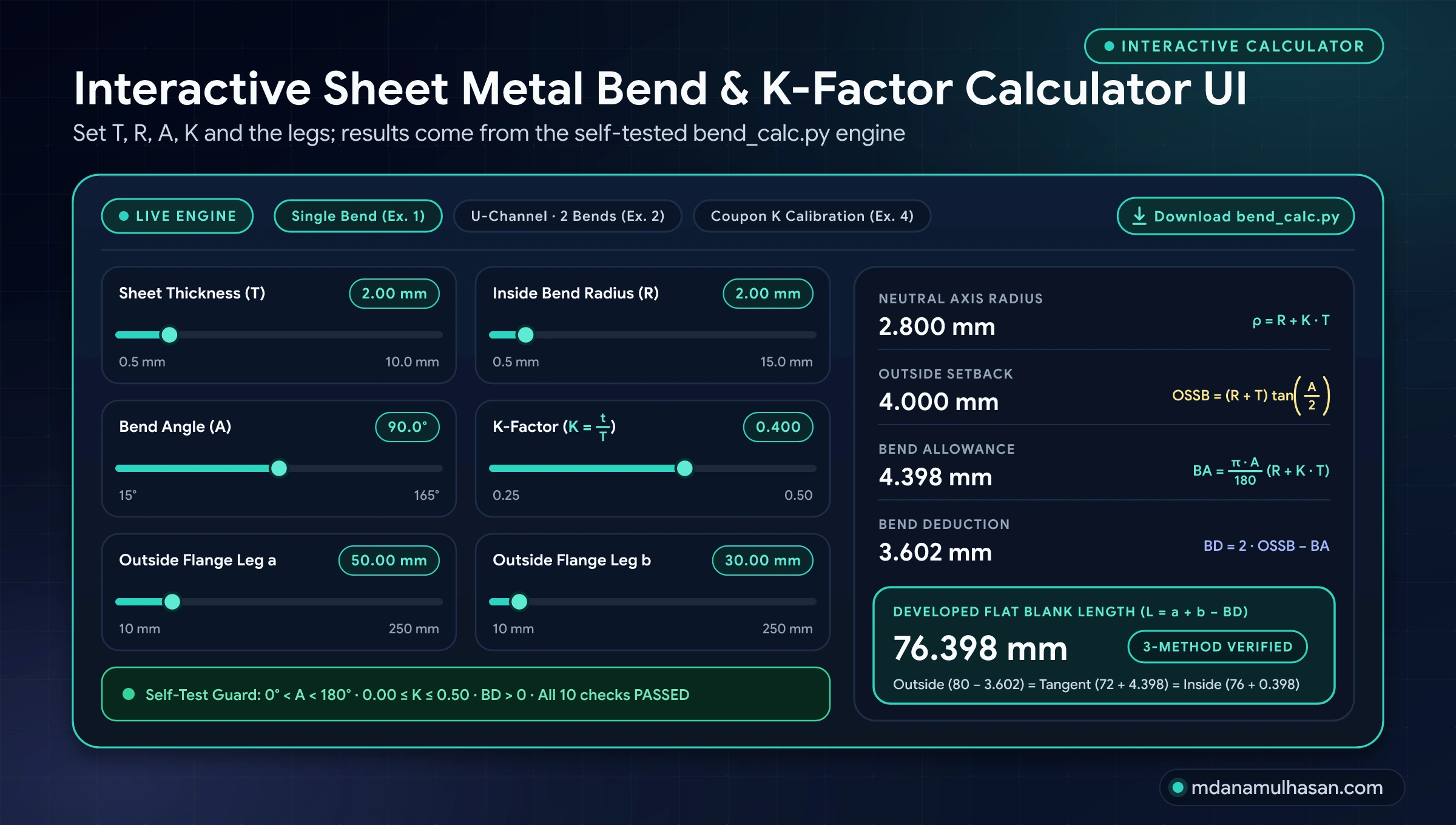
Everything above is packaged as a free tool: interactive calculators in the browser (bend allowance and flat length, coupon back-calculation, and a K-error cost estimator) and a zero-dependency Python module with a 10-check self-test. Use it from its own page instead of copying code out of an article: Sheet Metal Bend Calculator. For CAD automation and release gates, get the bend_calc.py module from the same page (it is free; you enter your name and email once); it validates inputs, supports all three flat-length methods and can emit JSON.
The results below are what the tool returns for this article’s worked examples.
| Example 1 (T = 2, R = 2, A = 90°, K = 0.40, legs 50 and 30) | Result |
|---|---|
| Neutral axis radius | 2.800 mm |
| Outside setback | 4.000 mm |
| Bend allowance | 4.398 mm |
| Bend deduction | 3.602 mm |
| Developed flat blank | 76.398 mm |
| Example 4 (coupon: T = 3, R = 3, A = 90°, L = 100, legs 52.75 and 52.75) | Result |
|---|---|
| Measured bend deduction | 5.500 mm |
| Recovered bend allowance | 6.500 mm |
| Calibrated | 0.3793 |
Checks the self-test runs
| Check | Why it matters |
|---|---|
| Example 1 gives , and to 12 digits | Pins the core formulas. |
| Outside, inside and tangent methods agree | Catches convention errors in the formulas. |
| BD equals at 90° | Confirms the closed form. |
| Small-angle limit of BD | Confirms the tangent behaviour near flat. |
| BD > 0 for every angle from 1° to 179° at K = 0.5 | Catches sign errors. |
| , , gives | Confirms the extreme case. |
| Calibration round trip recovers K | Confirms the back-calculation. |
| Tangent method on a mixed-direction (Z) part | Confirms it is valid for every bend sequence. |
| Zero thickness and bend angles of 0° or 180° are rejected | Prevents divide-by-zero and nonsense. |
| K outside 0 to 0.5 is rejected | Flags bad measurements. |
Rules I would put in an automated checker
- Reject the included angle by design. Name the input
bend_angleand add a unit test. Do not accept both. - Never hard-code K. Look it up. If no entry exists, fail loudly, not silently with a default.
- Carry the calibration date and coupon count with each K.
- Compare, then gate. Fail the release if CAD and calculator differ beyond your tolerance. Set that tolerance from your process capability, not from a number in an article.
- Use the tangent method internally. It is valid for every bend sequence.
- Log every input and every result. When a part fails inspection, you want to see which K it used.
- Treat a new coil, new tooling or a new supplier as a recalibration trigger.
Common mistakes
- Using the included angle in the formulas.
- Using the punch nose radius instead of the actual formed radius in air bending.
- Copying K from a table and assuming it matches your brake.
- Mixing outside, inside and tangent dimensions on one part.
- Applying the outside-dimension formula to a Z-bend or joggle.
- Using one K for every thickness and radius.
- Rounding BA and BD early. Round only the final flat length.
- Checking one bend and assuming the rest are fine. Errors multiply with bend count.
- Ignoring springback. Springback changes the angle you get for a given press stroke. It is an angle control problem, not a flat-length problem, but it is often mistaken for a K problem.
Quick checklist
- Is A the bend angle, not the included angle?
- Is R the actual formed inside radius?
- Does K come from calibration on this material, thickness, radius and tooling?
- Do the outside, inside and tangent calculations agree?
- Is BD positive and BA plausible against ?
- Does the CAD flat length match the calculator within your tolerance?
- Is the K source the same in CAD and in the calculator?
FAQ
What K-factor should I use?
There is no universal value. It depends on the material, the tooling, the bend radius and the process, so calibrate it on your own parts with a test coupon (the coupon mode of the calculator does this).
What is the difference between bend allowance and bend deduction?
BA is the length of the neutral axis through the bend. BD is what you subtract from the sum of the outside dimensions. They are linked by . Use BA with flat lengths and BD with outside dimensions.
Can K be greater than 0.5?
For conventional bending, a calibration result above 0.5 usually points to a measurement or radius error. Check your measurements before you trust it.
Why does my CAD flat length differ from my hand calculation?
Common causes: different K or a bend table in the CAD model, included angle used in the hand calculation, different inside radius, or a different dimensioning convention. Compare BA and BD per bend first.
What is the Y-factor?
A different way of expressing the same neutral axis position, used by some systems. . Convert before comparing numbers.
Do I need to recalibrate K often?
Recalibrate when material, thickness, tooling, process or supplier changes, and periodically as part of process control. The right interval depends on your process.
Does springback affect K?
Springback changes the final angle after the tool releases. It is handled by overbending or angle control. K describes the neutral axis position. Keep the two problems separate.
Is the tangent method really always valid?
Yes. It sums straight lengths and bend allowances and does not depend on which side the bends turn. The outside and inside formulas require all bends to turn the same way.
The verdict
K-factor sets the bend allowance. The bend allowance sets the bend deduction. The bend deduction sets the blank. Get K from measurement on your own tooling, use the bend angle consistently, store tangent lengths internally, and let an independent calculator audit the CAD flat pattern before anything is cut.
If you want help calibrating K, building a bend table, or wiring an audit step into your CAD release flow, reach out through the contact page on this site.
Engineering note: values for K, tolerances and tooling in this article are examples for explaining the maths. They are not recommendations for any material or machine. Verify with your own test bends and your tooling supplier before production use. CAD feature names and options vary by version, so check your vendor documentation.

Written by Md Anamul Hasan
Project Manager & Mechanical Engineer
Specializing in mechanical design automation, CAD API scripting (SolidWorks, NX Open), and Teamcenter PLM workflow engineering.